The table displays the total phase current for the immer-
sion heater at start up. If an immersion heater has already
been started and is not used for its full capacity the val-
ues in the table can be changed because the control
initially uses this immersion heater.
1x230V, F1155-6
Max phase current L1(A)Max electrical addition
(kW)
–0.0
2.20.5
4.31.0
6.51.5
8.62.0
10.82.5
13.03.0
15.23.5
17.34.0
19.54.5
1x230V, F1155-12
Max phase current L1(A)Max electrical addition
(kW)
–0
4.31
8.72
13.03
17.44
21.75
26.16
30.47
Emergency mode
When the heat pump is set to emergency mode (SF1 is
set to ) only the most necessary functions are activated.
■
The compressor is off and heating is managed by the
immersion heater.
■
Hot water is not produced.
NOTE
The switch (SF1) must not be moved to "" or
" " until F1155 has been filled with water.
Components in the product can be damaged.
Power in emergency mode
The immersion heater's output in emergency mode is
set with the dip-switch (S2) on the immersion heater
board (AA1) according to the table below. Factory setting
is kW for F1155.
1x230V for F1155-6
654321kW
offoffoffoffoffon0.5
offoffoffonoffoff1.0
offoffoffonoffon1.5
ononoffoffoffoff2.0
offonoffoffoffon2.5
offonoffonoffoff3.0
offonoffonoffon3.5
ononoffonoffoff4.0
ononoffonoffon4.5
1x230V för F1155-12.
654321kW
onoffoffoffoffoff1
offoffoffonoffoff2
onoffoffonoffoff3
offonoffonoffoff4
onoffoffonoffon5
offonoffonoffon6
ononoffonoffon7
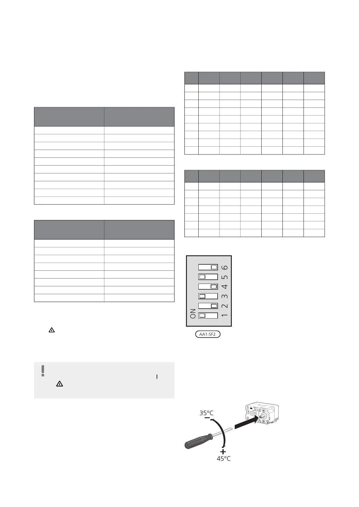
1x230V for F1155-6 / -12
The image shows the dip-switch (AA1-SF2) in the factory
setting, i.e. 3.5 kW for F1155-6 and 6 kW F1155-12 .
Emergency mode thermostat
The supply temperature in emergency mode is set using
a thermostat (FD1-BT30). It can be set to 35 (pre-set, for
example under floor heating) or 45 °C (for example radi-
ators).
LEK
LEK
För markvärme!
För frånluftsvärme!
25Chapter 5 | Electrical connectionsNIBE F1155
 Loading...


