Connections
NOTE
To prevent interference, unscreened commu-
nication and/or sensor to external connections
cables must not be laid closer than 20 cm to
high voltage cable when cable routing.
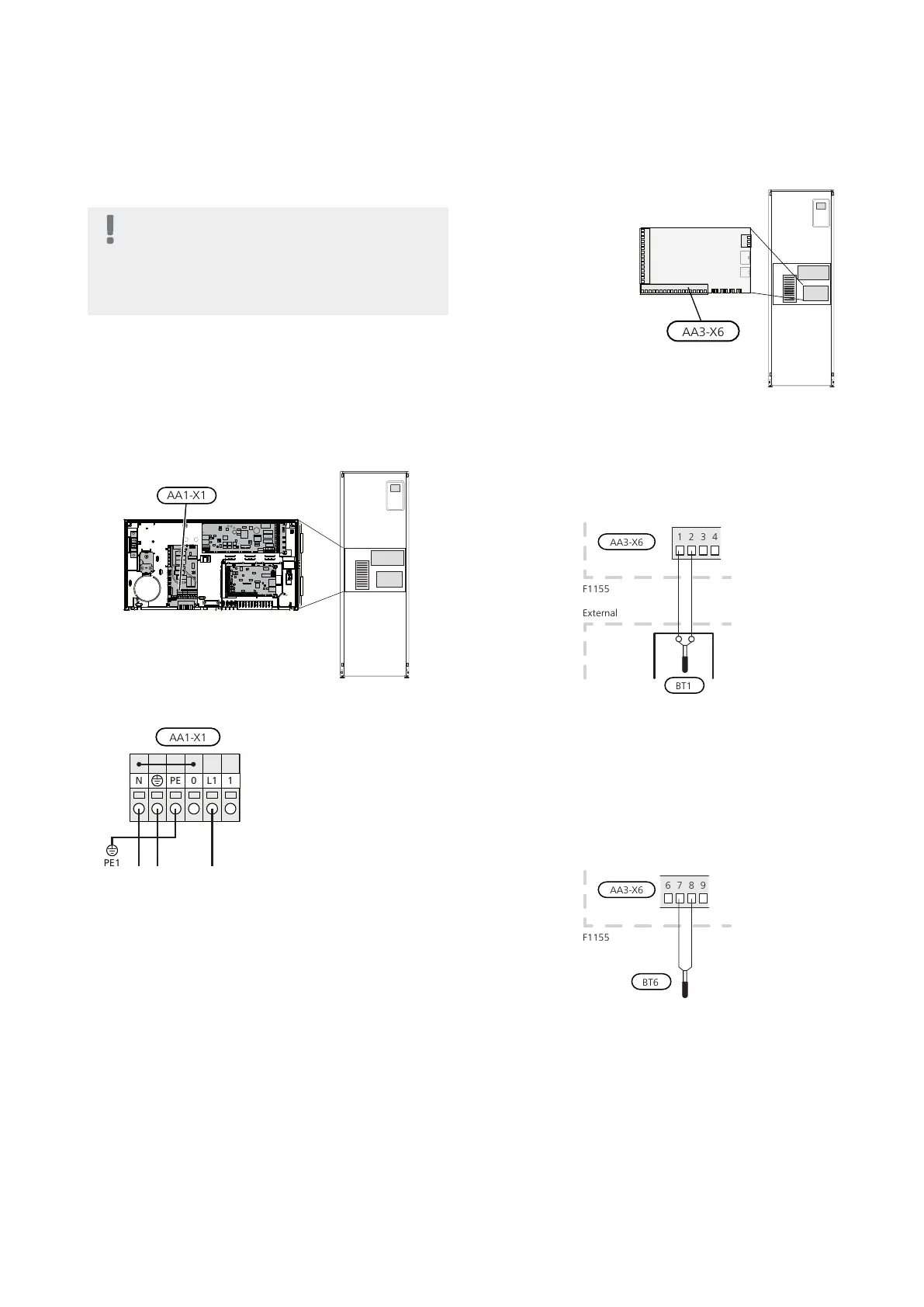
Power connection
F1155 must be installed with a disconnection option on
the supply cable. Minimum cable area must be sized ac-
cording to the fuse rating used. Enclosed cable for incom-
ing supply electricity is connected to terminal block X1
on the immersion heater board (AA1). All installations
must be carried out in accordance with current norms
and directives.
Connection 1x230V
If separate supply to the compressor and immersion
heater is required, see section "Switch for external
blocking of addition and/or compressor" on page 26.
Tariff control
If the voltage to the immersion heater and/or the com-
pressor disappears during a certain period, there must
also be blocking via the AUX-input, see "Connection
options - Possible selection for AUX inputs" page. 26
Connecting sensors
Connect the sensor(s) to
terminal X6 on input
board(AA3) according
to the instructions be-
low.
Outside sensor
Install the outdoor tem-
perature sensor (BT1) in
the shade on a wall fa-
cing north or north-
west, so it is unaffected
by the morning sun for
example.
Connect the sensor to terminal block X6:1 and X6:2 on
the input board (AA3). Use a twin core cable of at least
0.5 mm² cable area.
If a conduit is used it must be sealed to prevent condens-
ation in the sensor capsule.
Temperature sensor, hot water charging
The temperature sensor, hot water charging (BT6) is
placed in the submerged tube on the water heater.
Connect the sensor to terminal block X6:7 and X6:8 on
the input card (AA3). Use a 2 core cable of at least 0.5
mm² cable area.
Hot water charging is activated in menu 5.2 or in the
start guide.
Temperature sensor, hot water top
A temperature sensor for hot water top (BT7) can be
connected to F1155 via soft inputs for showing the water
temperature at the top of the tank.
See page 26 for connecting the sensor.
23Chapter 5 | Electrical connectionsNIBE F1155
 Loading...


