EasyManuals Logo

Nibe F1155 Series Installer Manual

Nibe F1155 Series
80 pages
To Next Page IconTo Next Page
To Previous Page IconTo Previous Page
Page #22 background imageLoading...
Page #22 background image
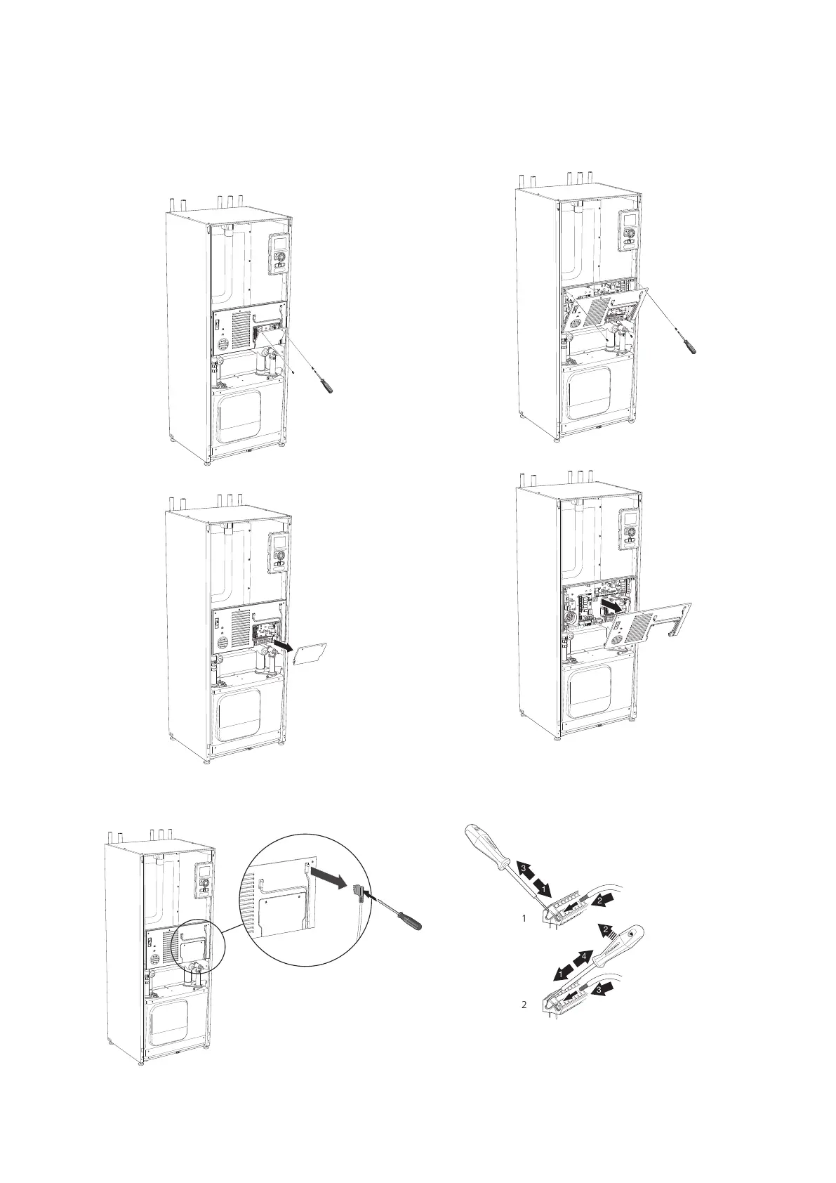
Removing the cover, input circuit board
1.
Unscrew the screws and angle out the cover.
L
E
K
L
E
K
L
E
K
L
E
K
2.
Pull off the cover.
L
E
K
L
E
K
L
E
K
L
E
K
Removing the hatch, electrical cabinet
1.
Disconnect the contacts.
L
E
K
2.
Unscrew the screws and angle out the cover.
L
E
K
L
E
K
L
E
K
L
E
K
3.
Pull off the cover.
L
E
K
L
E
K
L
E
K
L
E
K
Cable lock
Use a suitable tool to release/lock cables in the heat
pump terminal blocks.
LEK
1
1
2
2
3
3
1
2
3
3
4
1
2
LEK
1
1
2
2
3
3
1
2
3
3
4
1
2
1
2
NIBE F1155Chapter 5 | Electrical connections22

Other manuals for Nibe F1155 Series

Questions and Answers:

Question and Answer IconNeed help?

Do you have a question about the Nibe F1155 Series and is the answer not in the manual?

Nibe F1155 Series Specifications

General IconGeneral
RefrigerantR410A
Control SystemNIBE SMO 40
InstallationIndoor
Heating Capacity1.5-16 kW
Cooling CapacityNot applicable
Power Input CoolingNot applicable
EER CoolingNot applicable
Weight Outdoor UnitNot applicable
Dimensions Outdoor Unit (HxWxD)Not applicable
Dimensions Indoor Unit (HxWxD)600 x 620 mm

Related product manuals