General
All electrical equipment, except the outdoor sensors,
room sensors and the current sensors are ready connec-
ted at the factory.
■
Disconnect the heat pump before insulation testing
the house wiring.
■
If the building is equipped with an earth-fault breaker,
F1155 should be equipped with a separate one.
■
If a miniature circuit breaker is used this should have
at least motor characteristic “C”. See page 64 for fuse
size.
■
Electrical wiring diagrams for the heat pump, see sep-
arate installation handbook for electrical wiring dia-
grams.
■
Communication and sensor cables to external connec-
tions must not be laid close to high current cables.
■
The minimum area of communication and sensor
cables to external connections must be 0.5 mm² up to
50 m, for example EKKX or LiYY or equivalent.
■
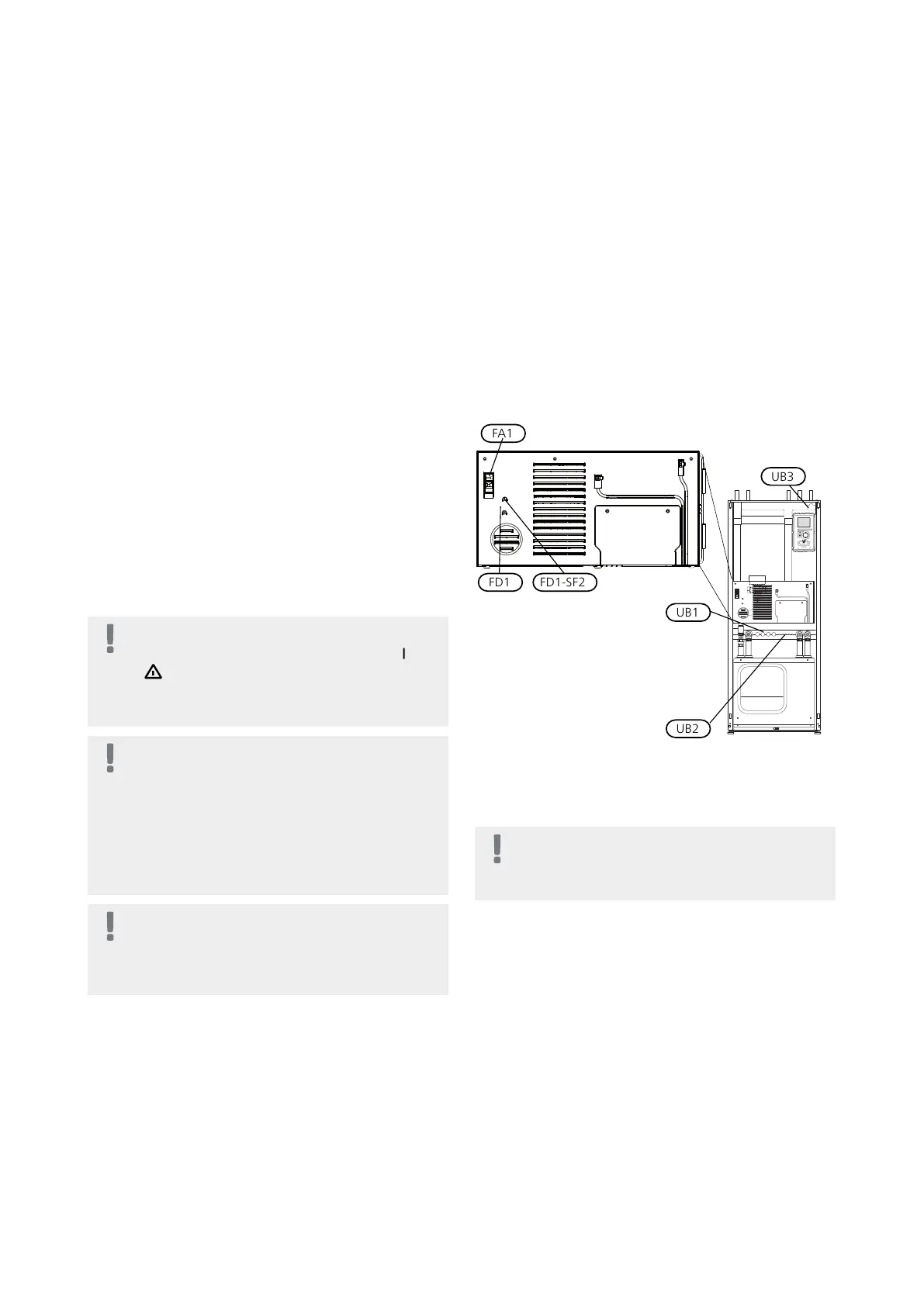
When cable routing in F1155, cable grommets (e.g.
UB1-UB3, marked in image) must be used. In UB1-UB3
the cables are inserted through the heat pump from
the back to the front.
NOTE
The switch (SF1) must not be moved to "" or
" " until the boiler has been filled with water.
Component parts of the product can be dam-
aged.
NOTE
Electrical installation and service must be car-
ried out under the supervision of a qualified
electrician. Cut the current with the circuit
breaker before carrying out any servicing.
Electrical installation and wiring must be car-
ried out in accordance with the stipulations in
force.
NOTE
Check the connections, main voltage and phase
voltage before the machine is started, to pre-
vent damage to the heat pump electronics.
Miniature circuit-breaker
The heat pump operating circuit and some of its internal
components are internally fused by a miniature circuit
breaker (FA1).
Temperature limiter
The temperature limiter (FD1) cuts the power to the
electric additional heat if the temperature exceeds 89°C
and is reset manually.
Resetting
The temperature limiter (FD1) is accessible behind the
front cover. Reset the temperature limiter by pressing
the button (FD1-SF2) using a small screwdriver.
Temperature limiter, compressor
The temperature limiter (FD2) cuts the current supply to
the soft starter if the temperature rises above 88 °C and
is manually reset.
Resetting
The temperature limiter (FD2) is accessible behind the
front cover. Reset the temperature limiter by pressing
the button (FD2-SF2) using a small screwdriver.
Accessibility, electrical connection
The plastic cap of the electrical boxes is opened using a
screwdriver.
NOTE
The cover for the input card is opened without
a tool.
21Chapter 5 | Electrical connectionsNIBE F1155
5 Electrical connections
 Loading...


