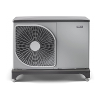
LIST OF COMPONENTS F2040
Pipe connections
Shut-off valve, liquid sideQM36
Shut-off valve, gas sideQM37
Connection, heating medium out from F2040,
G1" (Ø28 mm)
XL1
Connection, heating medium in to F2040,
G1" (Ø28 mm)
XL2
Sensors etc.
High pressure pressostatBP1 (63H1)
Temperature sensor, heating medium return
line
BT3
Temperature sensor, condenser supply lineBT12
Temperature sensor, hot gasBT14 (Tho-
D)
Temperature sensor, fluid pipeBT15
Temperature sensor 1, evaporatorBT16 (Tho-
R1)
Temperature sensor, suction gasBT17 (Tho-
S)
Temperature sensor, ambientBT28 (Tho-
A)
Low pressure transmitterBP2 (LPT)
High pressure sensorBP4
Temperature sensor 2, evaporatorTho-R2
Electrical components
Communication boardAA23
Fuse for external heating cable (250 mA), max
45 W.
AA23-F3
DIP switch, addressing of outdoor unitAA23-S3
Terminal block, KVRAA23-X1
Terminal block, communication from indoor
module
AA23-X4
Communication with TBAA23-X100
Compressor heaterEB10 (CH)
Drip tray heaterEB11 (DH)
Main fuse compressor unitF
FanGQ1 (FM01)
FanGQ2 (FM02)
Control boardPWB1
Inverter boardPWB2
Filter boardPWB3
EMC filter for inverterRF2
EMC filter for incoming supplyRF3
Terminal block, incoming supply and communic-
ation with board AA23
TB
Cooling components
4-way valveQN2 (20S)
CompressorGQ10 (CM)
Expansion valve, coolingQN3 (SM1)
Expansion valve, heatingQN1 (SM2)
Evaporator (copper pipe with aluminium flange)EP1
CondenserEP2
Drying filterHS1
Miscellaneous
Type platePF1
Serial numberPF3
Cable gland, incoming supplyUB1
Cable grommet, communicationUB2
Cable gland, heating cable (EB14)UB3
Cable, incoming supplyW1
Designations in component locations according to standard IEC 81346-2. Designations within brackets according to the supplier’s standard.
NIBE F2040Chapter 3 | The heat pump design22

 Loading...