Pipe connections
FIGHTER 410P
For the Installer
12
Pipe installation must be carried out in accordance with
current norms and directives.
The system requires a low-temperature dimensioning of
the radiator circuit. At DUT, the highest recommended
temperatures are 55 °C on the flow line and 45 °C on
the return line.
When the circulation pump is running, the flow in the
radiator circuit must not be completely stopped.
The total volume is 240 litres, with 170 litres in the water
heater and 70 litres in the boiler section.
The pressure vessel in the FIGHTER 410P is approved
for max 9.0 bar (0.9 MPa) in the water heater and
2.5 bar (0.25 MPa) in the double shell section.
Overflow water from the evaporator collection tray and
safety valves goes via non-pressurised collecting pipes
to a drain so that hot water splashes cannot cause inju-
ry. These non-pressurised collecting pipes shall not be
used for anything else. A discharge pipe from the tundish
(108) connected to the expansion relief valve (47) (safe-
ty valve) shall also be connected to a drain in the same
way.
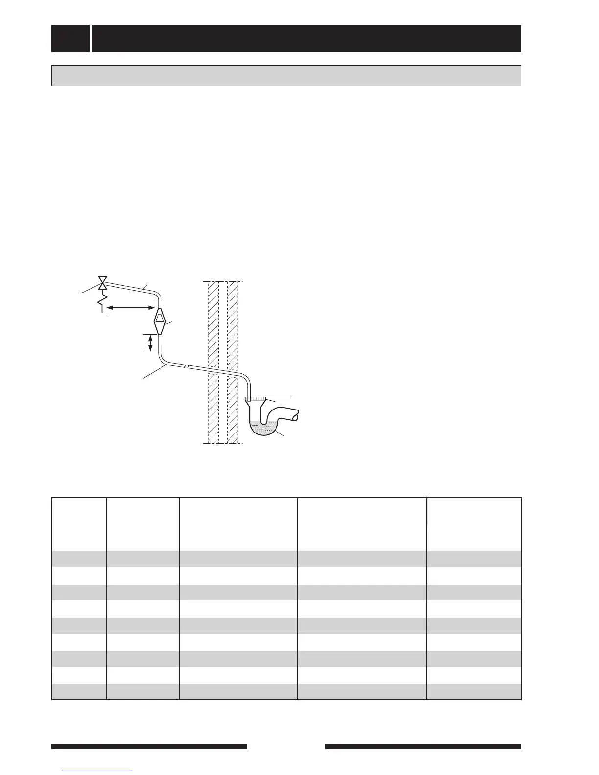
Discharge pipes from tundishes shall have av vertical
section of pipe at least 300 mm long, before any elbows
or bends in the pipework. See following picture.
General
If the vertical distance, 300 mm, is hard to fulfil a heigh-
tening console is available as an accessorie. No valve
should be fitted between the pressure reduction valve
(expansion valve) and the storage cylinder.
<G3> / 4 22 mm 35 mm up to 18 m 1,4 m
<G3> / 4 22 mm 28 mm up to 9 m 1,0 m
G1 28 mm 35 mm up to 9 m 1,4 m
<G3> / 4 22 mm 42 mm up to 27 m 1,7 m
G1 28 mm 54 mm up to 27 m 2,3 m
G1 28 mm 42 mm up to 18 m 1,7 m
Valve Minimum size of Minimum size of discharge Maximum resistance allowed, Resistance created
outlet size discharge pipe pipe from tundish expressed as a lenght by each elbow
of straight pipe or bend
(i.e. no elbows or bends)
G1 / 2 15 mm 22 mm up to 9 m 0,8 m
G1 / 2 15 mm 35 mm up to 27 m 1,4 m
G1 / 2 15 mm 28 mm up to 18 m 1,0 m
Table sizing of copper discharge pipe for common temperature relief valve outlet sizes.