Pipe connections
13
For the Installer
FIGHTER 410P
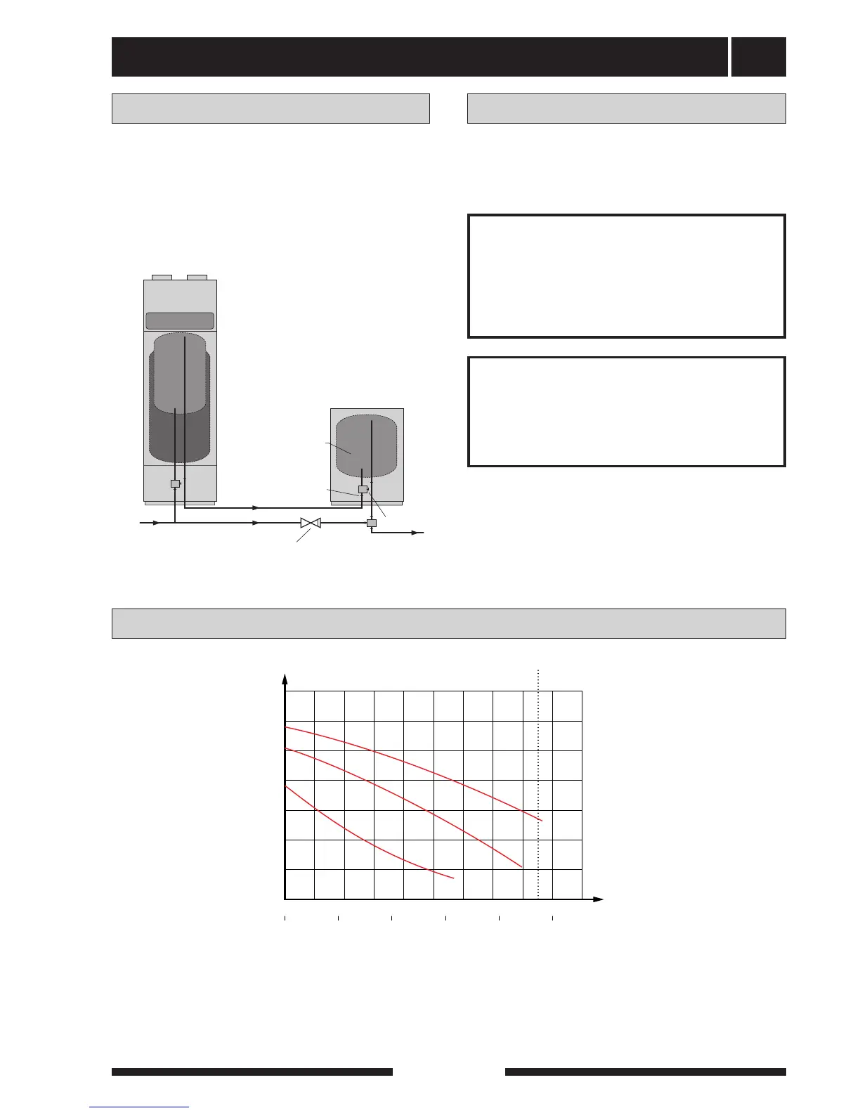
Hot and cold water are connected to pos (74) (hot
water) and (73) (cold water).
The heat pump should be supplemented with an elec-
tric water heater if a bubble pool or other significant
consumer of hot water is installed.
Tap water connection
KV
VV
VV
INK KV-ANSL
PROPPNING
KV
VV-BEREDARE
MED "DELAT"
VENTILKOPPEL
BACKVENTIL
KV
VV FRÅN VÄRMEPUMP
VV
INK KV-ANSL
PROPPNING
VV-BEREDARE
MED "DELAT"
VENTILKOPPEL
BACKVENTIL
KV
VV
VV
INK KV-ANSL
PROPPNING
KV
VV-BEREDARE
MED "DELAT"
VENTILKOPPEL
BACKVENTIL
Water heater
COMPACT
Heat pump
FIGHTER 410P
Pump and pressure drop diagrams
Pumpkapacitet
Flöde
Tillgängligt tryck, kPa
Internt tryckfall i panna
(inklusive armatur)
Tillgänglig pumpkapacitet
(pannans interntryckfall fråndraget)
3
2
1
0 500 1000
0
1500 2000
4
l/h
P
5
6
Interner Druckverlust in der Heizung
(einschließlich Armatur)
Zugängliche Pumpenkapazität
(interner Heizdruckverlust abgezogen)
3
2
1
kPa
kPa
60
50
40
30
20
10
0
mWs
l/s
0,50,40,30,20,10
Höchstmenge:1700 l/h
Höchstmenge:1700 l/h
3
2
1
0 500 1000
0
1500 2000
4
l/h
l/h
l/h
P
5
6
Internal pressure drop in boiler
(including fittings)
Available pump capacity
(less the internal pressure drop of the boiler)
3
2
1
wg
10
200
0
0
20
400
30
600
40
800
50
1000
60
1200
70
1400 1600 1800 2000
50
40
30
20
10
0
m
Flow
l/s
0,50,40,30,20,10
l/s
0,50,40,30,20,10
Max flow: 1700 l/h Max flow: 1700 l/h
Max flöde: 1700 l/h
l/s
0,50,40,30,20,10
Flow, l/h
Available pump capacity, kPa
10
200
0
0
20
400
30
600
40
800
50
1000
60
1200
70
1400 1600 1800 2000
Menge
Vorhandener Druck, kPa
10
200
0
0
20
400
30
600
40
800
50
1000
60
1200
70
1400 1600 1800 2000
Available pressure, kPa
Max flow: 1700 l/h
Flow
The enclosed expansion vessel (106) for tap water
shall be installed in the tap water circuit after the pres-
sure reduction valve.
Expansion vessel, tap water
Warning to the
installer!
This installation is subject to building
regulation approval, notify the Local
Authority of intention to install.
Warning to the
installer!
Use only manufacturer’s
recommended replacement parts.
EXISTING VALVE
COUPLING
PARTED
INCOMING COLD
WATER
CONNECTION
CHECK VALVE
PLUGGED