The delivered output in the diagram is calculated when dimension-
ing the heating system 55/45 °C respective 35/25 °C (floor heat-
ing).
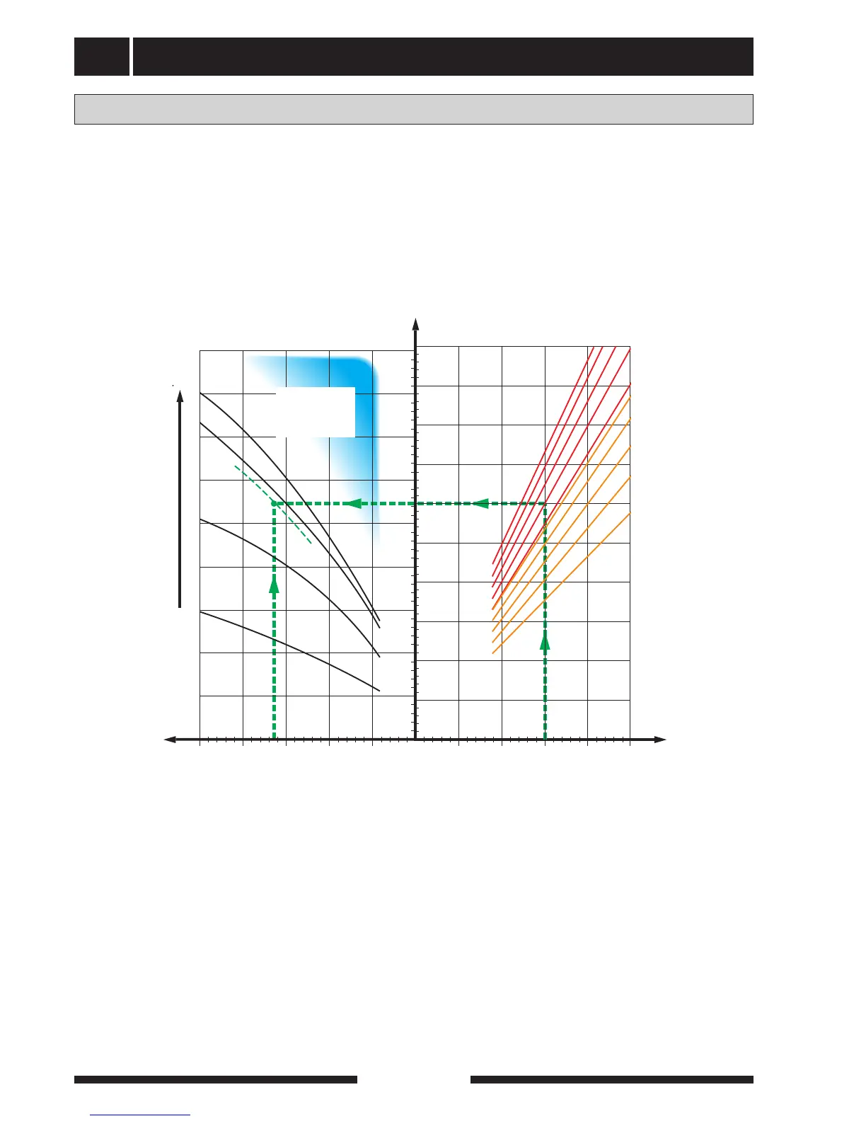
The supply air battery is connected in parallel with the
radiator circuit and heats the house’s supply air. The addi-
tional output is determined according to the diagram.
The water flow through the supply air battery is set by
means of a trim valve (81).
When, for example, the supply air flow rate is set to
150 m
3
/h and DUT is -20 °C a setting is obtained, at a
pump pressure (= pressure drop battery circuit) of
3.3 mvp (33 kPa), of 2.8 on the trim valve.
This means the trim valve should be opened 2.8 turns
from the closed position. At the same time it can be read
that the battery supplies the supply air with approximately
3.0 kW of additional output at -20 °C
NOTE! Vent the battery using the venting screw (5)
repeatedly in order to ensure the circulation through the
battery.
Supply air battery
Fully open
Trim valve setting
(No. opened turns)
Pressure drop
radiator/battery
circuit
Risk for low
supply
temperature
Water flow
Emitted output
Supply flow