Selection of the ventilation capacity is carried out in
connection with ventilation adjustment by connecting
the three white cables from the exhaust air fan respec-
tive the three black cables from the supply air fan to
the appropriate outlets on the terminal block (22). See
the illustration Ventilation connection — Fan diagram.
The cables correspond to fan and position as follows:
Black cable 094: Supply air fan, position A (reduced)
Black cable 096: Supply air fan, position B (normal)
Black cable 098: Supply air fan, position C (forced)
White cable 095: Exhaust air fan, position A (reduced)
White cable 097: Exhaust air fan, position B (normal)
White cable 099: Exhaust air fan, position C (forced)
NOTE!
The same outlet must never be used
for both fans.
Setting the fan capacity
(black)
(white)
(black)
(white)
(black)
(white)
Normally the immersion heater is permitted to run
even if the compressor has switched of because its
stop temperature has been reached (under the condi-
tion that the immersion heater is connected via the
operating mode selector). Furthermore, the flow tem-
perature is permitted to be as high as 65 °C.
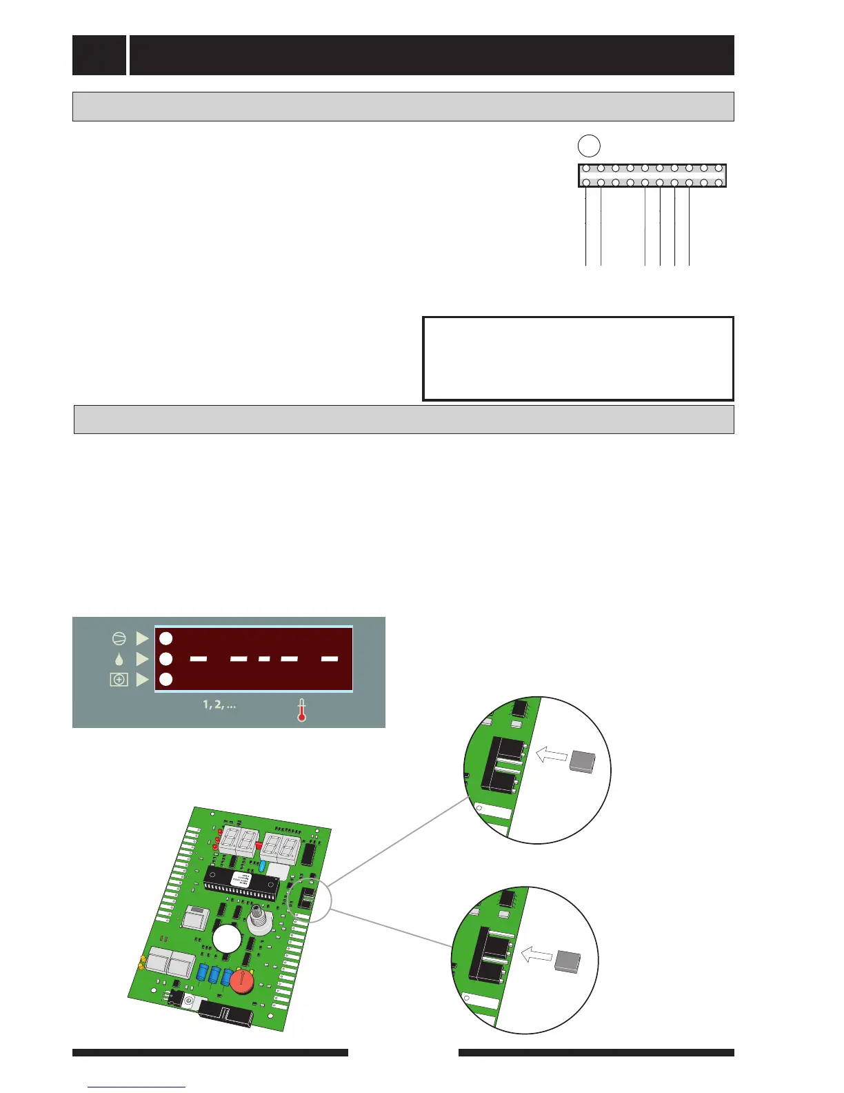
These functions can be deactivated by moving the strap
from pins 1 and 2 to pins 2 and 3 as illustrated.
The numerical display will now show horizontal lines,
otherwise vertical.
Once the strap is in position on pins 2 and 3 the
immersion heater is only permitted to run when the
compressor is operational (except in defrosting mode).
In addition, the flow temperature is limited to maxi-
mum 60 °C.
Art.nr. 611822
2
1
bar
3
04
2
1
bar
3
04
2
1
bar
3
04
Transparent, blåfärgad film (ej hål).
67,5
57.25
26,3
86,3
92,7
126,8
129,8
132,8
145,2
336
41
19,2
83
90.5
111
98,6
523
10,5
Ø 52,8
53,5
135,3
130,7
15
70,5
135,3
r=4,5
37
23
9
2 st Ø 4,5, transparent, ofärgad film (ej hål).
OBS! Endast halv cirkel (radie=11)
Slits på baksidan
De 8 grårastrerade ytorna (Ø22)
skall ej förses med häftämne.
49,5
84,4
85,7
186,3
196,8
42,5
52
161
Ø 13
Ø 18,5
Hål 16 x 31
Hål 16 x 16
313,2