FIGHTER 410P
Electrical circuit diagram
For the Installer
27
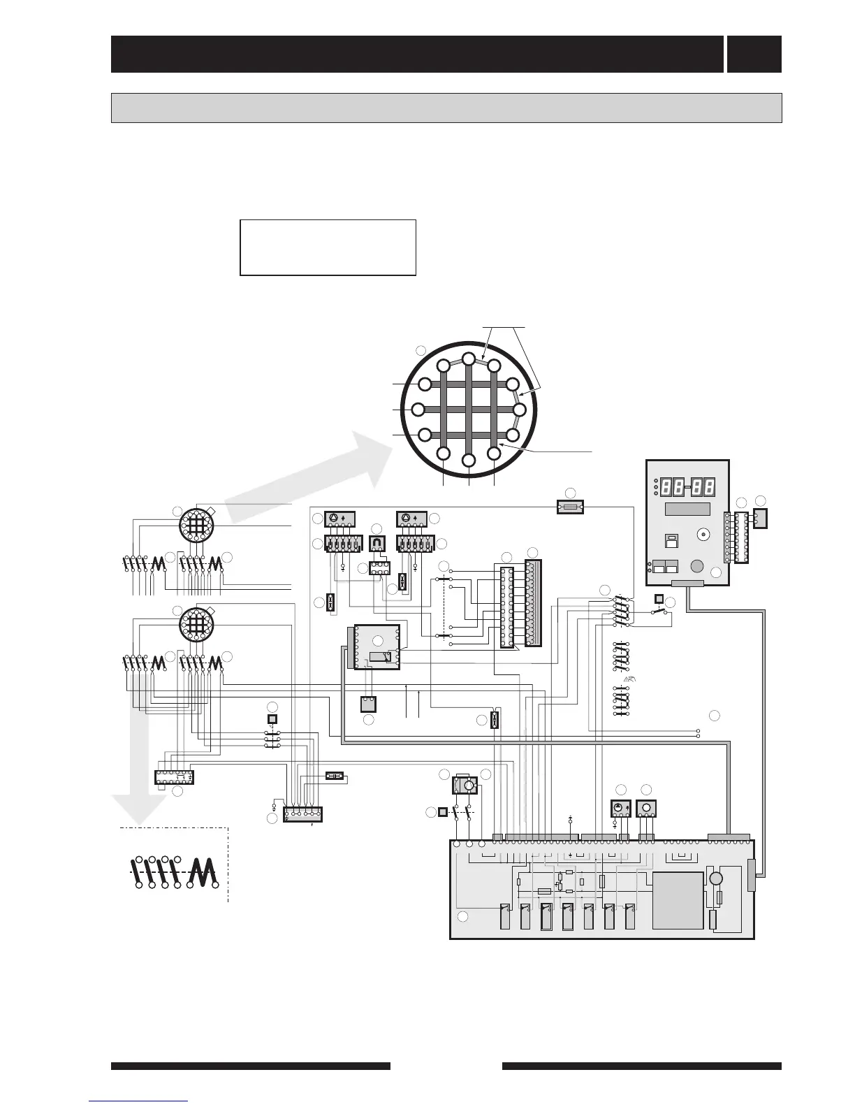
6.0 kW to 8.0 kW
Move cable “67A1-12” from the parked position, posi-
tion “14” on contactor (67) to position “A1” on the same
contactor, see output option “8 kW”.
Contact 10 controls step 1
Contact 67 controls step 2
Changing the output