General pipe
connections
Pipe installation must be carried out in accordance with
current norms and directives.
Lowest permitted temperature of incoming brine is -8°C.
Pipes and other cold surfaces must be insulated with
diffusion-proof material to prevent condensation.
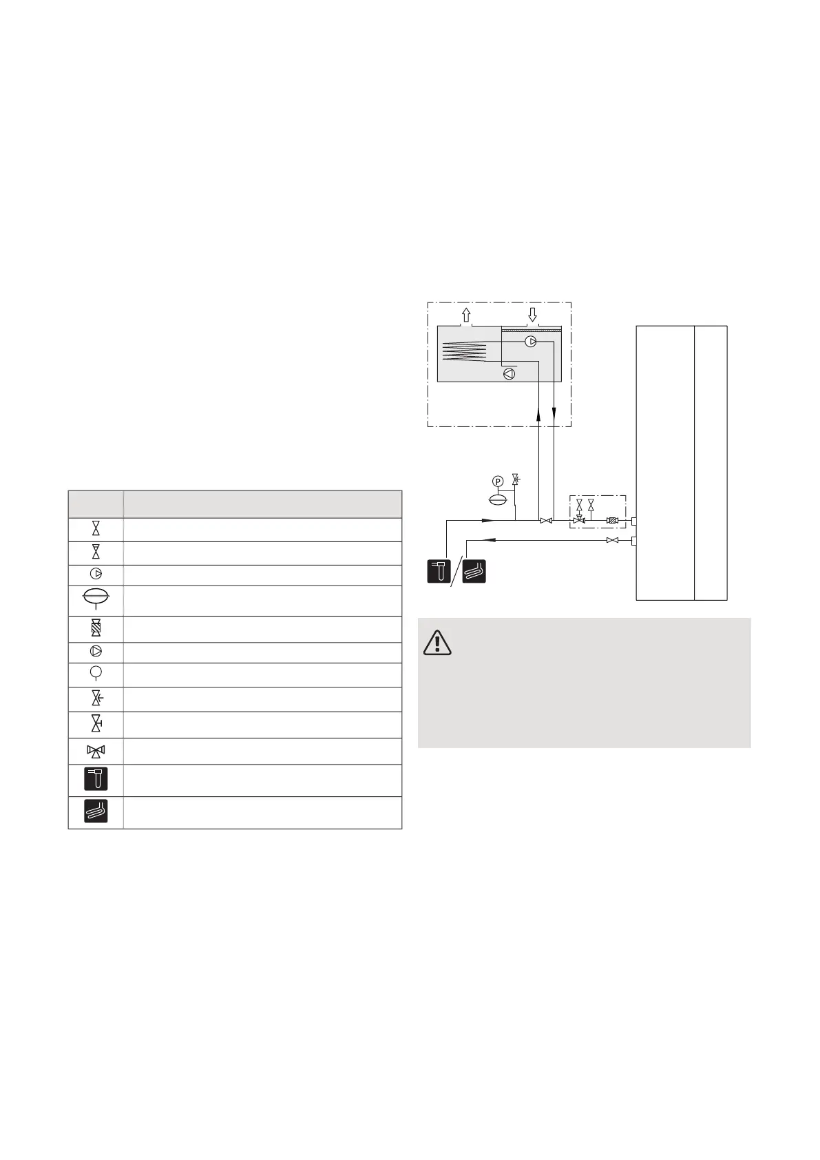
SYMBOL KEY
MeaningSymbol
Shut-off valve
Non-return valve
Circulation pump
Expansion vessel
Filterball
Fan
Pressure gauge
Safety valve
Trim valve
Manual reversing valve/shunt
Bore hole
Ground collector
OUTLINE DIAGRAM
NOTE
Venting may be necessary during installation
and after a period of use. Venting takes place
through vent valve (QM21). When venting, set
the switch for the circulation pump (SF2) to
position ”0”.
COMPATIBLE NIBE HEAT PUMPS
NIBE FLM ventilates the building and preheats the brine,
regardless of which ground source heat pump is in-
stalled, but when NIBE FLM is installed together with
a compatible ground source heat pump, it is possible to
adjust settings and read off sensor values etc. in the
heat pump’s display.
Compatible products
• F1345
• F1355
• F1245
• F1255
• F1145
• F1155
NIBE FLMChapter 4 | Pipe and ventilation connections10
4 Pipe and ventilation
connections

 Loading...


