Dimensions and pipe
connections
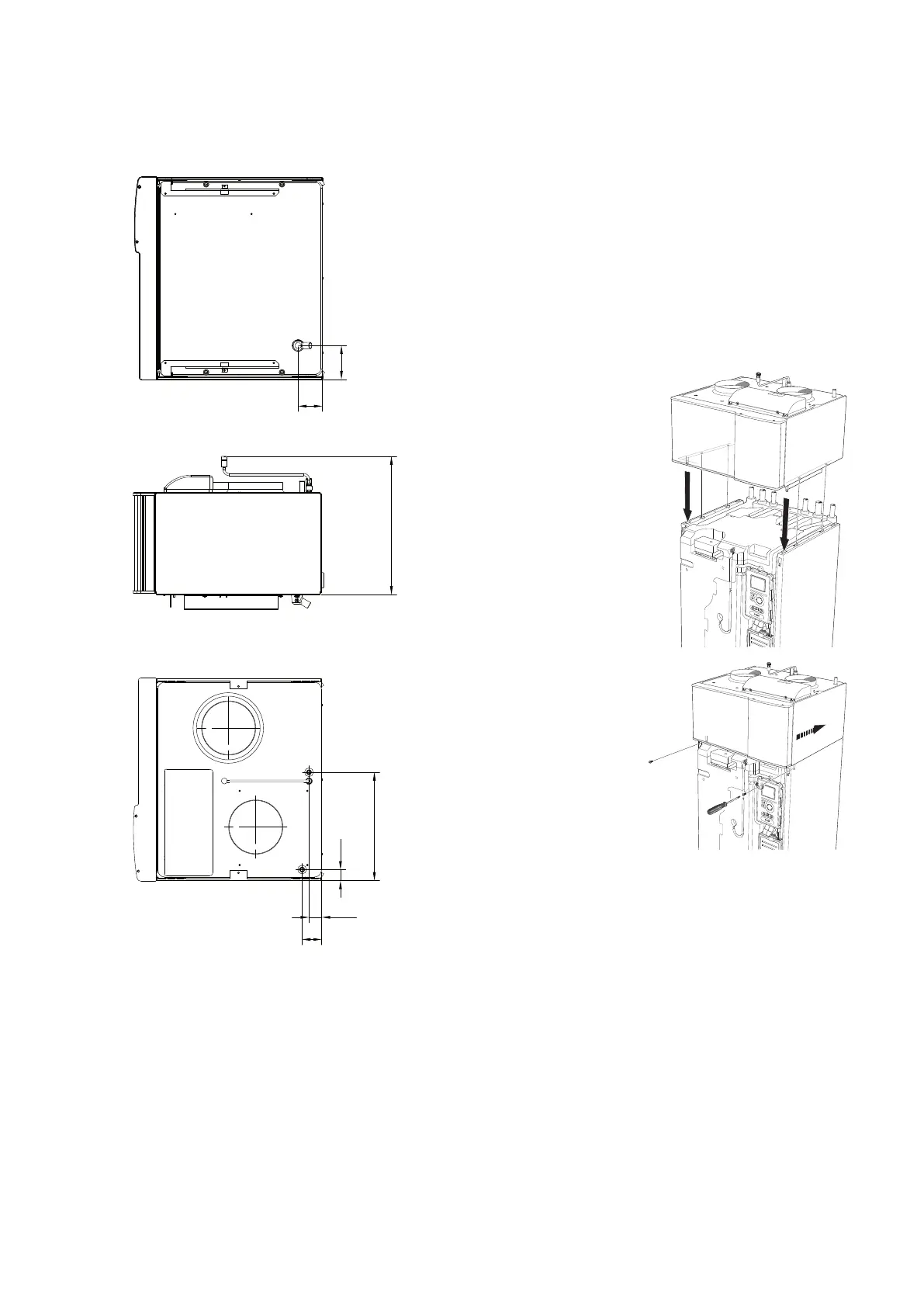
Mounting
CONNECTING TO F1145/F1155/F1245/F1255
1.
Remove the front cover from the heat pump.
2.
Remove the top panel from the heat pump (installed
with 6 x screws).
3.
Install NIBE FLM from the top and slide into position.
4.
Secure NIBE FLM with the 2 supplied screws.
5.
Connect brine and ventilation pipes.
6.
Reinstall the front cover on the heat pump.
NIBE FLM can also be installed freestanding on brackets.
11Chapter 4 | Pipe and ventilation connectionsNIBE FLM

 Loading...


