Supplied components
Non-return valve (RM1)
Ø 32 mm
Trim valve (RN1)
Ø 15 mm
2 x screws (T25) for in-
stalling NIBE FLM on NIBE
heat pump
Condensation water hose
Ø 20 mm
LOCATION
The bag of supplied items is placed on top of NIBE FLM.
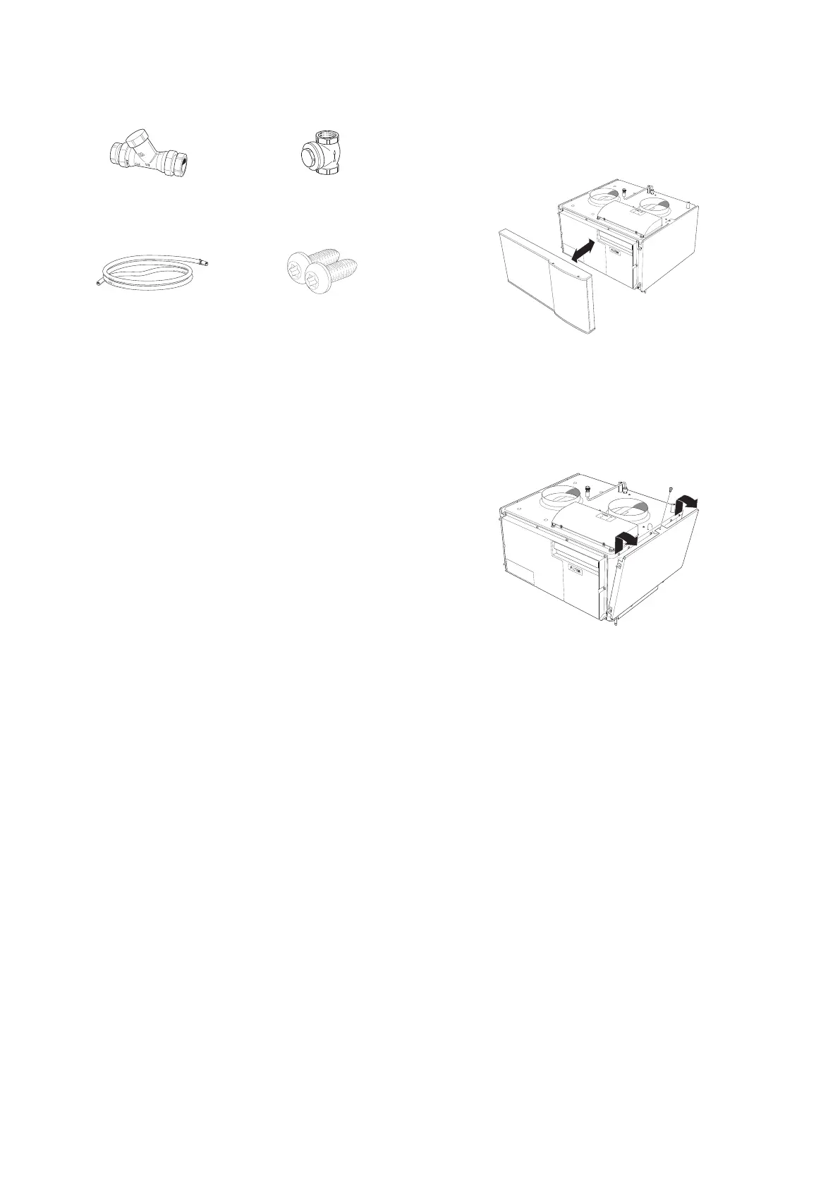
Removing the covers
FRONT COVER
1.
Remove the service cover by pulling it straight out.
SIDE COVERS
1.
Undo the screws at the upper edge
2.
Lift the side hatches upwards and twist the cover
outwards slightly.
3.
Assembly takes place in the reverse order.
7Chapter 2 | Delivery and handlingNIBE FLM

 Loading...


