STARTING-UP WITH ANOTHER HEAT PUMP
1.
Set the main switch (SF1) and the switch for the
circulation pump (SF2) on NIBE FLM to position “1”.
2.
Disconnect the PWM cable from terminal AA5-X2:7-
8. Insulate the wires properly.
3.
Check that the fan (GQ2) and the circulation pump
(GP2) are in operation.
4.
Set the speed of the fan using the potentiometer
(SF3).
5.
Start the heat pump.
Starting-up with ventilation only
In cases where NIBE FLM is to be run with ventilation
only, e.g. before the brine side is ready for connection.
In this mode the circulation pump must be switched off.
1.
Follow points 1-6 under “Starting with another heat
pump”, but leave the switch for the circulation pump
(SF2) in “0” position.
2.
When the brine side is connected, set the switch
for the circulation pump (SF2) to position “1”.
Starting-up with another heat pump
Start the brine pump in the heat pump (see your heat
pump's handbook).
The brine flow over NIBE FLM is regulated by the trim
valve (RN1), so that the temperature difference for brine
in and out from NIBE FLM is 2–4°C. The temperature
is measured using external test equipment.
Adjustments are made when the heat pump is running.
Temperature difference applies at 20 °C room temper-
ature and 0 °C in the brine.
The brine flow through NIBE FLM will be from 0.1 l/s
(360 l/h) to 0.15 l/s (540 l/h) at the above temperature
differences, depending on the ventilation flow.
When the heat pump is at a standstill the internal circu-
lation pump in NIBE FLM gives from 0.085 l/s (306 l/h)
to 0.125 l/s (450 l/h) in the return charging flow to the
collector. This applies to a heat pump with approximately
4 kW rated output. For a 15 kW heat pump the corres-
ponding flow is from 0.09 l/s (324 l/h) to 0.14 l/s (504
l/h).
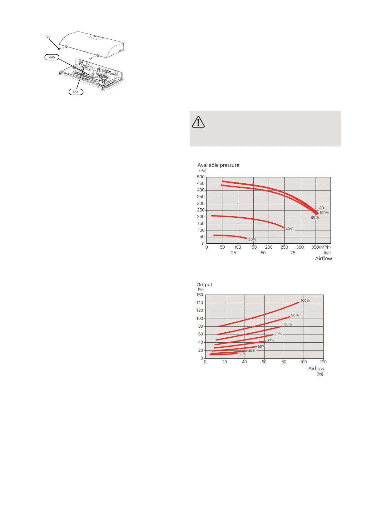
SETTING THE VENTILATION
Ventilation must be set according to applicable stand-
ards. If NIBE FLM is connected to a compatible heat
pump, the setting is adjusted in menu 5.1.5. Otherwise
the ventilation capacity is set via potentiometer (AA5-
SF3).
Even if ventilation is roughly set at installation it is im-
portant that a ventilation adjustment is ordered and
permitted.
NOTE
Order a ventilation adjustment to complete the
setting.
Ventilation capacity
0
0 50 100 150 200 250 300 350
50
100
150
200
250
300
350
400
450
500
Tillgängligt tryck
(Pa)
(m
3
/h)
(l/s)
Luftflöde
20%
80-
100%
60%
40%
25
50 75
Available pressure
Airflow
Power direct current fan
0
0 20 40 60 80 100 120
20
40
60
80
100
120
140
160
Effekt
(w)
Luftflöde
(l/s)
100%
80%
60%
40%
30%
50%
70%
90%
NIBE FLMChapter 6 | Commissioning and adjusting24

 Loading...


