CONNECTING TO ANOTHER HEAT PUMP
1.
Install NIBE FLM on brackets.
2.
Connect brine and ventilation pipes.
Brine side
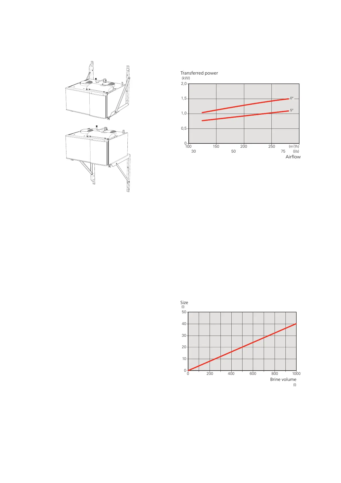
OUTPUT TRANSFER TO BRINE
Output transfer to brine
0
100 150 200 250
0,5
1,0
1,5
2,0
Överförd effekt
(kW)
(m
3
/h)
(l/s)
Luftflöde
0°
5°
30 50 75
The diagram shows the power that is transferred from
the ventilation air to the brine at 0°C and 5°C, and applies
to an air temperature of +20°C and 50% relative air hu-
midity.
EXPANSION VESSEL
The brine circuit must be provided with pressure expan-
sion vessel (CM3). If there is a level vessel (CM2), this
should be replaced. The brine side must be pressurised
to at least 0.5 bar.
To prevent malfunctions, the pressure expansion vessel
should be dimensioned as set out in the diagram. The
pressure expansion vessel covers the temperature range
from -10°C to +20 °C for the brine at a pre-pressure of
0.5 bar and with the safety valve’s opening pressure set
at 3 bar.
Expansion vessel
0
0 200 400 600 800 1000
10
20
30
40
50
Storlek
(l)
Köldbärarvolym
(l)
NIBE FLMChapter 4 | Pipe and ventilation connections12

 Loading...


