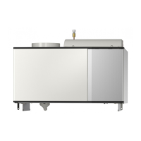
Pipe connections
Connection, brine in, compression ring Ø 15 mmXL6
Connection, brine out, compression ring Ø 15 mmXL7
Ventilation connection exhaust air, Ø 160 mmXL31
Ventilation connection extract air, Ø 160 mmXL32
Drip-pan drainXL40
HVAC components
Heat exchangerEP16
Circulation pump, brineGP2
Venting brineQM21
Sensors etc.
Temperature sensor, exhaust airBT20
Temperature sensor, extract airBT21
Temperature sensor, collector inBT26
Temperature sensor, collector outBT27
Electrical components
Accessory cardAA5
Dip switchAA5-S2
Joint cardAA100
Switch, position 0 - 1, main switchSF1
Switch, position 0 - 1, circulation pumpSF2
PotentiometerSF3
Cord with connection plugW1
Control cableW6
Ventilation
Exhaust air fanGQ2
Exhaust air filterHQ10
Miscellaneous
Type platePF1
Designations at component positions according to standard EN 81346-
2.
9Chapter 3 | The design of the exhaust air moduleNIBE FLM

 Loading...