General
All electrical equipment is connected at the factory.
• Disconnect NIBE FLM before insulation testing the
house wiring.
• For the exhaust air module wiring diagram, see page
34.
• Signal cables to external connections must not be laid
close to high current cables.
• If the supply cable is damaged, only NIBE, its service
representative or similar authorised person may re-
place it to prevent any danger and damage.
NOTE
Electrical installation and service must be car-
ried out under the supervision of a qualified
electrician. Electrical installation and wiring
must be carried out in accordance with the
stipulations in force.
Connections
F1345 has different electrical connection versions de-
pending on when the heat pump was manufactured. To
check which electrical connection applies to your F1345,
check the designation "2.0" visible above the right hand
side of the terminal block as illustrated.
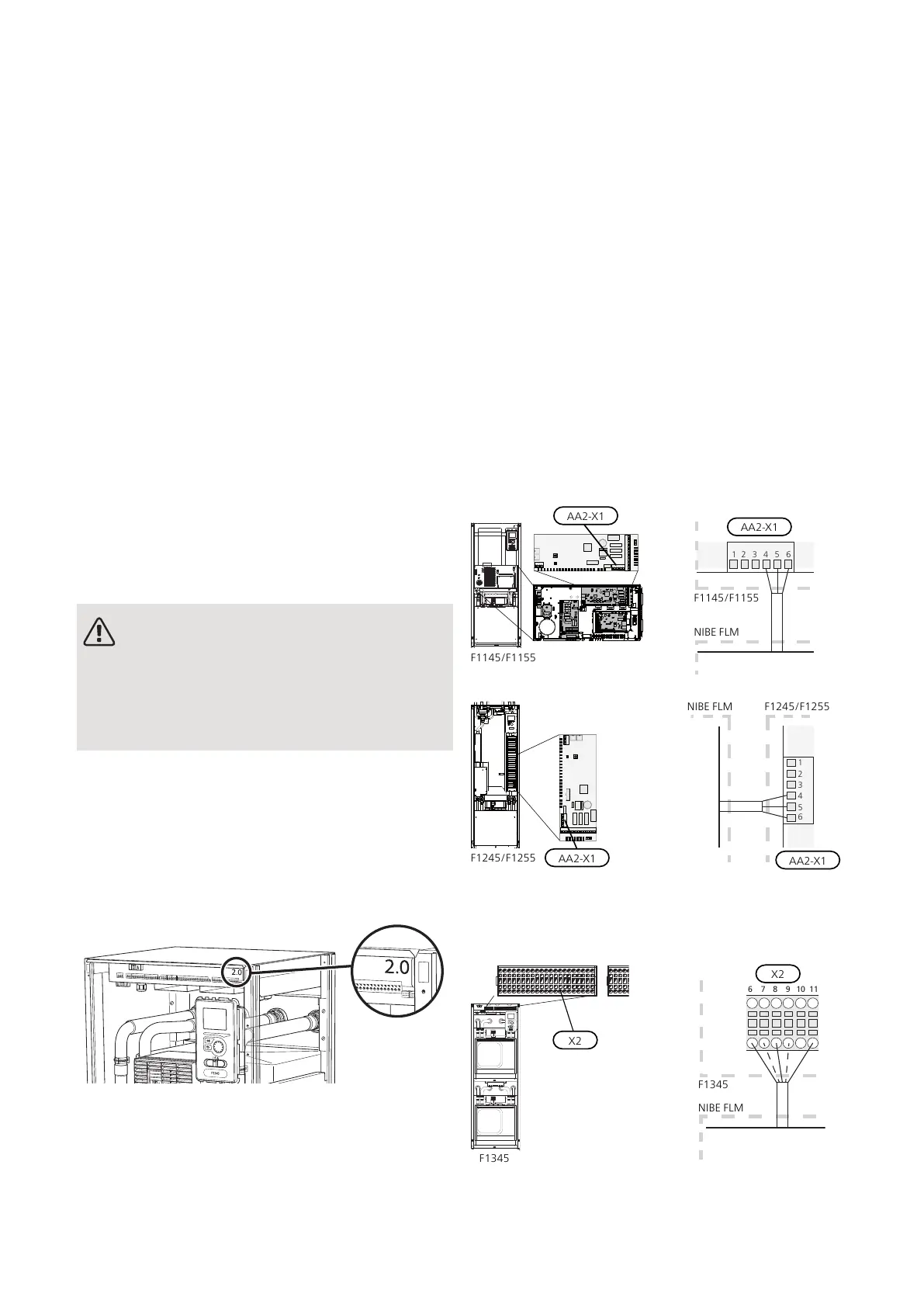
CONNECTING TO COMPATIBLE HEAT PUMP
Connection of supply to NIBE FLM no. 1
In cases where NIBE FLM is installed together with a
compatible heat pump, it is possible to connect the
supply for NIBE FLM no. 1 on the terminal block in the
heat pump. If this is the case, remove the plug on the
connection cable (W1) and then connect the cable to
the base board (AA2) terminal block X1:4-6 in
F1145/1155/F1245/1255 or on terminal blocks X2:6-9
and X2:11 in F1345, on terminal block AA101:X5 in
F1345 2.0/F1355.
F1145/F1155/F1245/F1255
X1:4 Yellow/green, X1:5 Blue, X1:6 Brown
AA2-X1
F1145/F1155
NIBE FLM
AA2-X1
NIBE FLM F1245/F1255
F1345 without 2.0
X2:6 or X2:7 Brown, X2:8 or X2:9 Blue, X2:11 Yellow/green
17Chapter 5 | Electrical connectionsNIBE FLM
5 Electrical connections

 Loading...


