F1345 with 2.0/F1355
X5:1 Brown, X5:4 Blue, X5:7 Yellow/green
X5
F1345 2.0/
F1355
NIBE FLM
L1
-X3
-X4
1 2
3
-AA101 -AA101
N
L2
L3
1 2
3
4
5
6
7
8
9
-X5
1 2
3
4
5
6
7
8
9
-X6
-X7
-X8 -X9
-FC1
-AA101 -AA101
-AA101 -AA101 -AA101
1 2
3
4
1 2
3
1 2
3
1 2
3
4
5
-X10
A B A B
-AA3-X7
K1
-AA101
K2
K3
C C
NO
NC
K4
C
NO
NC
QN10 GP16
L N L L L N N N L N L N
PE
PE
6
7
8
9 10
1112
13
14
15
16
17
18
1920
2122
12V
A B
13
14
-BE1
-GP16
-BE2
-BE3
AUX 4
AUX 5
1 2
3
4
5
6
7
8
9 10
1112
13
14
15
-AA3
-X6
0-10V
-EP14
-EP15
-BF1
16
17
18
2
-AA3
-X22
-AA3
-AA3
-X20
-X21
1
3
12
3
-X23
-BT1
-BT50
-BT25
-BT6
AUX 1
AUX 2
AUX 3
-BT7
-BT71
2.0
1 2
3
4
5
6
7
8
9
-X5
-FC1
-AA101
L L L
N N N
Connecting the supply to NIBE FLM no. 2-4
NIBE FLM no. 2-4 connects to an earthed single phase
wall socket or a permanent installation. For permanent
installations, NIBE FLM has to be preceded by a circuit
breaker with at least a 3 mm breaking gap.
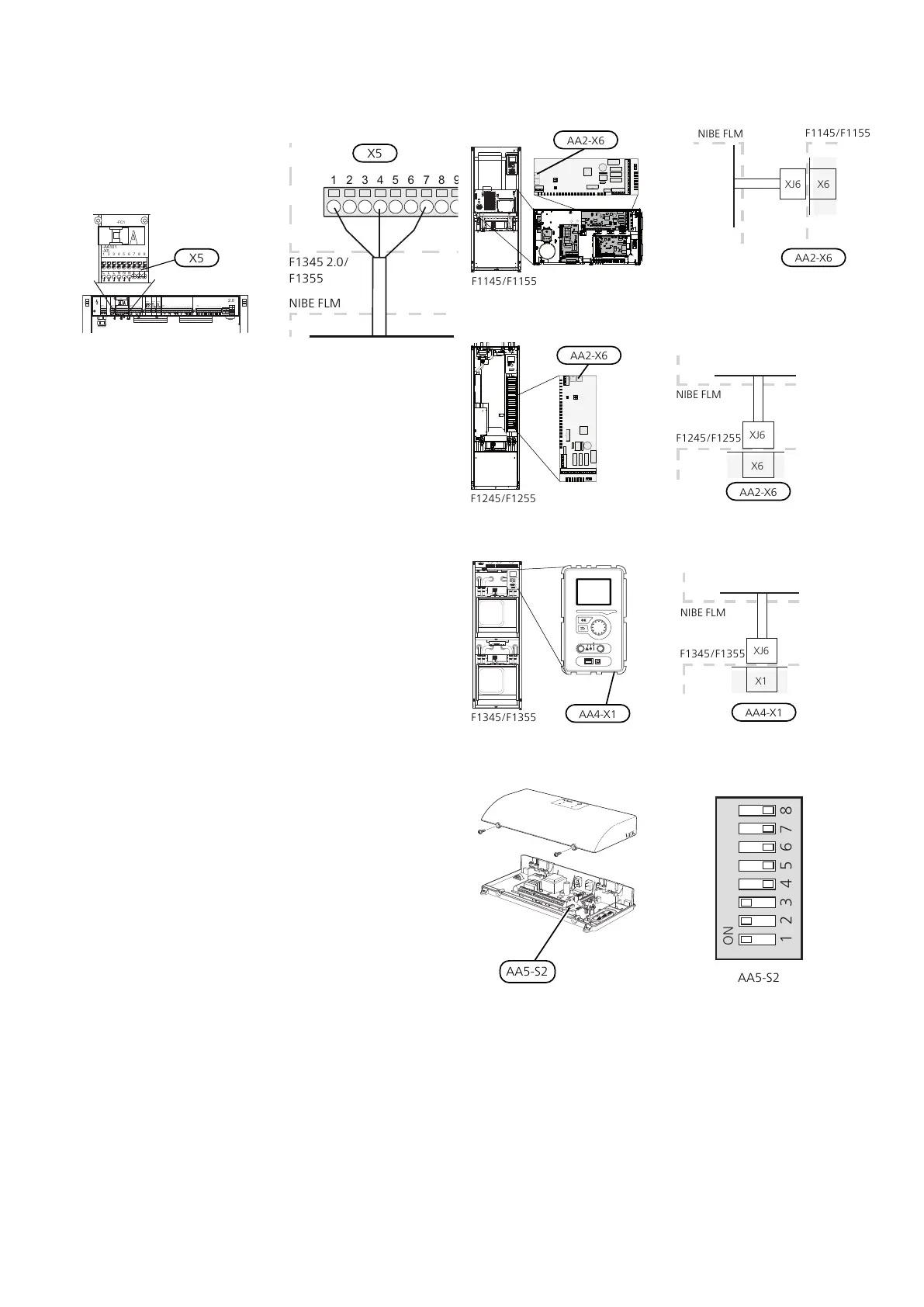
Connecting the communication to NIBE FLM
no. 1
F1145/F1155/F1245/F1255: The control cable (W6) with
connector XJ6 connects to contact X6 on the base board
(AA2).
F1345/F1355: The control cable (W6) with connector
XJ6 connects to contact X1 on the display board (AA4).
F1145/F1155
AA2-X6
F1145/F1155
NIBE FLM
F1245/F1255
AA2-X6
NIBE FLM
F1245/F1255
F1345/F1355
AA4-X1
F1345/F1355
NIBE FLM
The DIP switch (AA5-S2) has to be set as follows.
NIBE FLMChapter 5 | Electrical connections18

 Loading...


