Addition
Immersion heater (EB1)
The immersion heater can be set up to a maximum of
9 kW.
Delivery setting is 9 kW.
The immersion heater output is divided into 7 steps.
These 7 steps can then be restricted by BT63 as below.
No. of permitted stepsTemp BT63 (°C)
0>80
1>77
2>74
3>72
No restriction<72
Max. output
As there are regulations that determine the maximum
permitted electrical output for heating a building, the
immersion heater's maximum output is locked to
comply with these regulations.
One week after setting maximum output, the system
locks permanently at this value and the display unit
must be replaced if one later needs to increase the
maximum output.
Heating mode
During heating operation the immersion heater is
controlled by the degree minute calculation.
RemarksFactory
setting
NameMenu
9 kWMax electrical
output
5.1.12
Degree minute
deficit for start
of additional
heat.
700 DMstart addition4.9.3
100 GMdiff. between
additional
steps
Hot water operation
All additional heat must have been stepped out before
changing to hot water, see calculating hot water de-
mand.
When shifting back to heating, the additional heat step
must be stepped in as indicated by DM.
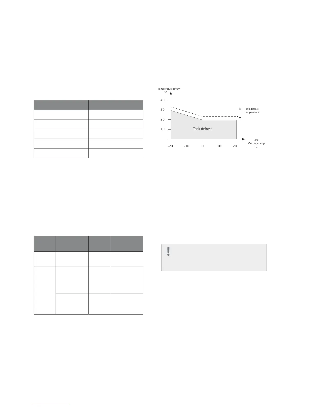
Function during defrosting
If BT6 or EB101-BT3 is less than Tank defrost temp (see
image).
Hot water is prioritised until Tank defrost temp has
been reached.
QN 10 towards hot water and additional heat is used
until the tank defrost temp + 5K has been reached.
Conditions for tank defrosting depending on the value for -BT3
Load monitor
The current sensors are connected to AA3-X4:1-4.
Function:
■
If any of the internal phases exceed the set value and
the phase sequence is not detected, electrical power
is disconnected from one of the internal phases. Be-
cause the phase sequence is not detected this can
mean that the incorrect phase sequence is disconnec-
ted, so that the output is still too high. The heat pump
continues by disconnecting another phase, until the
current does not exceed the set value. If the current
still exceeds the set value when all internal phases
are disconnected, the same process is performed for
external additional heat, if applicable and is set to
step-controlled additional heat.
NOTE
Do not disconnect the external additional
heat if it is set to give additional heat in one
step.
.
■
If the phase sequence is detected the electrical out-
put is disconnected in the phase that exceeds the set
value. This will also handle any external additional
heat.
■
If disconnecting the phases does not work, the heat
pump will finally disengage.
■
Reconnection occurs when the current has fallen to
a value low enough to permit reconnection.
17Chapter 4 | Description of functionsNIBE™ VVM 320

 Loading...


