Home
Nibe
Control Unit
VVM 320
Technical Manual
Page 54 (Alarm 70 - Perm. Com.error Input Card)
Nibe VVM 320 - Alarm 70 - Perm. Com.error Input Card
88 pages
Manual
To Next Page
To Next Page
To Previous Page
To Previous Page
Loading...
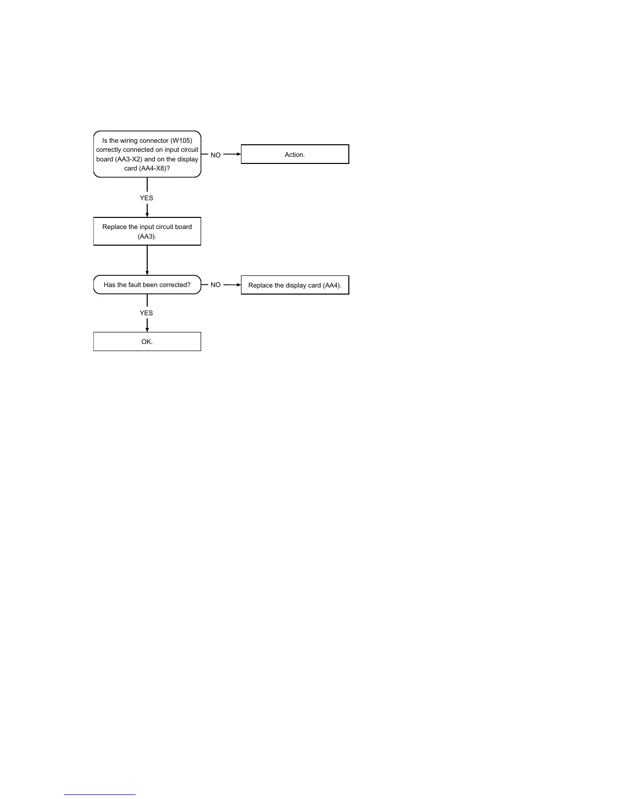
Alarm
70
-
perm.
com.error
input
card
Is
the
wiring
connector
(W105)
correctly
connected
on
input
circuit
board
(AA3-X2)
and
on
the
display
card
(AA4-X8)?
YES
YES
Has
the
fault
been
corrected?
Replace
the
input
circuit
board
(AA3).
Replace
the
display
card
(AA4).
NO
Action.
NO
OK.
NIBE™
VVM
320
Chapter
6
|
T
roubleshooting
52
53
55
Table of Contents
Main Page
Default Chapter
3
Table of Contents
3
Important Information
4
Document Information
4
Safety Information
4
Symbols
4
Marking
4
Serial Number
4
Contact Information
5
Indoor Module's Design
6
VVM 320
6
Pipe Connections
7
HVAC Components
7
Sensors Etc
7
Electrical Components
7
Miscellaneous
7
System Description Principle of Operation
8
Principle of Operation
8
Pipe Connections
8
HVAC Components
8
Sensors Etc
8
System Diagram
9
Description of Functions
10
Menu Tree
10
Operating Status
13
Hot Water
15
Heating
17
Cooling
18
Scheduling
18
Addition
19
Load Monitor
19
External Connection Options
20
Circulation Pumps
21
Supply Pump Exercise
24
Valves
24
Valve Exercising
24
Floor Drying
24
Uplink
24
Smart Grid (SG)
25
Usb
26
Accessories
28
Nibe™ VVM
29
System Description
8
4 Descriptionoffunctions
10
Component Description
37
Components
37
Sensors
41
Data Temperature Sensor
41
Electronics
42
Immersion Heater Card (AA1)
42
Base Card (AA2)
42
Input Circuit Board (AA3)
42
Display Unit (AA4)
43
Troubleshooting
44
Troubleshooting Alarm List
44
Alarm List
44
A-Alarm
44
B Alarm
48
Troubleshooting Guide
51
Alarm 1 - Sensor Fault
51
Alarm 2, 3, 6, 31 - Sensor Fault
52
Alarm 33-38 - Sensor Fault
53
Alarm 70 - Perm. Com.error Input Card
54
Alarm 71 - Perm. Com.error Input Card
55
Function Check, Components
56
Relay Test - Forced Control
56
Function Check, Circulation Pumps
57
Component Replacement
58
Basic
58
Removing the Covers
58
Accessibility, Electrical Connection
58
Main Components
61
Replacement of Immersion Heater
61
Replacing the Circulation Pump GP1
64
Replacing the Circulation Pump GP6
66
Replacement of Reversing Valve QN 10
68
Circuit Board and Electronics
71
Immersion Heater Card (AA1)
71
Base Card (AA2)
72
Input Circuit Board (AA3)
73
Display Unit (AA4)
74
Technical Data
75
Electrical Circuit Diagram, 3 X 400V
75
Dimensions and Setting-Out Coordinates
80
Technical Specifications
81
3X400V
81
Index
82
Other manuals for Nibe VVM 320
User Manual
92 pages
Installer Manual
88 pages
Related product manuals
Nibe FLM
24 pages
Nibe SAM 40
20 pages
Nibe SMO 20
76 pages
Nibe SMO 40
92 pages
Nibe OPT 10
40 pages
Nibe SCU 10
32 pages
Nibe EME 20
56 pages
Nibe SAM 42
20 pages
Nibe SMO S40
20 pages
Nibe RMU S40
80 pages
Nibe SMO 20 UK
64 pages
Nibe MODBUS 40
44 pages

 Loading...


