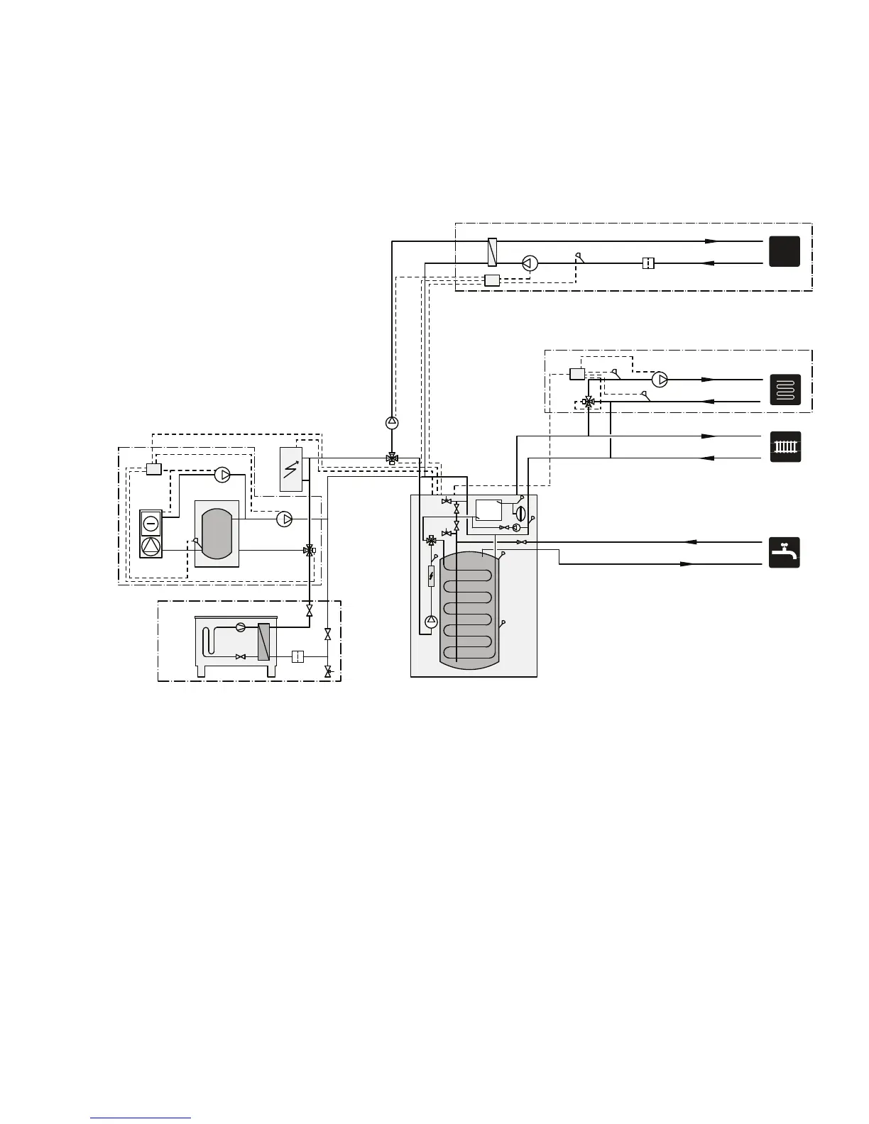
EasyManuals Logo

Nibe VVM 320 Technical Manual

Nibe VVM 320
88 pages
To Next Page IconTo Next Page
To Previous Page IconTo Previous Page
Page #9 background imageLoading...
Page #9 background image
System diagram
Outline diagram
-EB1
-GP9
-BT51
-HQ4
-EP5
-AA25
-CL11
-CL11-QN19
-CL11-GP12
POOL
-CP10
-QN12
-AA25
-EQ1
-GP13
-GP12
-BT64
-BT3
-BT2
-EP21
-GP20
-QN25
-AA25
-FL10
-QM41
-QM40
-HQ1
-EB101
-EB15
Explanation
Pool packageCL11
Unit boxAA25
Temperature sensor, poolBT51
Exchanger, poolEP5
Pool, pumpGP9
Charge pump, poolGP12
Particle filterHQ4
Three way valve, poolQN19
VVM 320EB15
Heat pumpEB101
Safety valveFL10
Particle filterHQ1
Shut-off valveQM40
Shut-off valveQM41
Climate system 2EP21
Unit boxAA25
Temperature sensor, heating medium, flowBT2
Temperature sensor, heating medium, returnBT3
Circulation pump, heating medium, lower shuntGP20
Mixing valve, additionQN25
Active cooling module ACS 310EQ1
Unit boxAA25
Temperature sensor, cooling, supply lineBT64
Single jacket accumulator tank, coolingCP10
Charge pumpGP12
Circulation pump, coolingGP13
Three way valve cooling/heatingQN12
Miscel-
laneous
Extra electric additional heatEB1
7Chapter 3 | System descriptionNIBE™ VVM 320

Table of Contents

Other manuals for Nibe VVM 320

Questions and Answers:

Question and Answer IconNeed help?

Do you have a question about the Nibe VVM 320 and is the answer not in the manual?

Nibe VVM 320 Specifications

General IconGeneral
Dimensions (HxWxD)1800 x 600 x 615 mm
Power Supply230 V
Frequency50 Hz
Protection classIP21
Compatible withNibe heat pumps
DisplayTouch display
Smart Home IntegrationYes, via NIBE Uplink
Operating temperature0°C to +45°C
Relative humidityMax. 95 %
TypeControl unit for heat pumps

Related product manuals