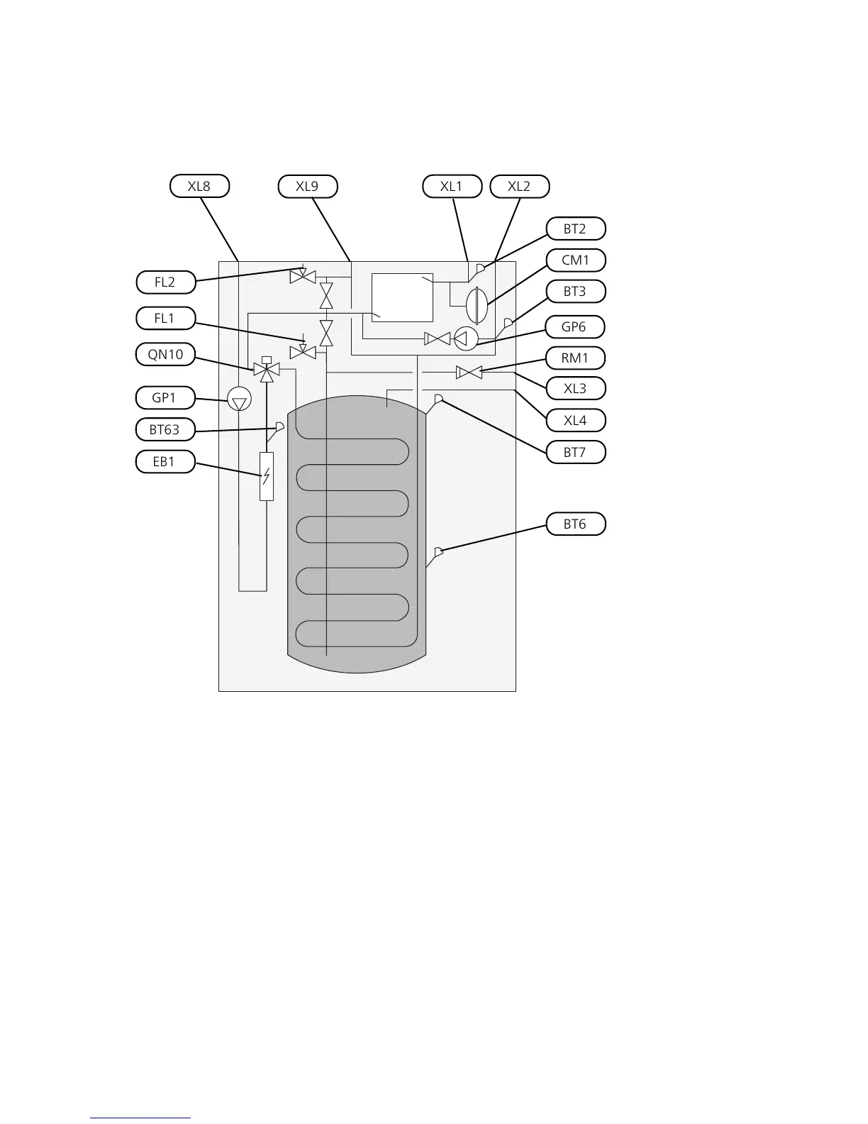
Pipe connections
Connection, heating medium supply line Ø22
mm
XL1
Connection, heating medium return line Ø22
mm
XL2
Connection, cold water Ø22 mmXL3
Connection, hot water Ø22 mmXL4
Connection, docking in heating medium Ø22
mm
XL8
Connection, docking out heating medium Ø22
mm
XL9
HVAC components
Expansion vessel, closed, heating mediumCM1
Safety valve, water heaterFL1
Safety valve, heating mediumFL2
Circulation pumpGP1
Circulation pump, heating mediumGP6
Reversing valve, climate system/water heating,
flow line
QN10
Check valve, cold waterRM1
Sensors etc.
Manometer, heating systemBP5
Temperature sensors, heating medium flowBT2
Temperature sensors, heating medium returnBT3
Temperature sensor, hot water, chargingBT6
Temperature sensor, hot water, topBT7
Temperature sensor, heating medium supply
after immersion heater
BT63
Designations in component locations according to
standard IEC 81346-1 and 81346-2.
NIBE™ VVM 320Chapter 3 | System description6
3 System description

 Loading...


