Circulation pumps
Heating medium pump (GP1)
The heating medium pump GP1 is active if heat produc-
tion is permitted and intermittent is not selected in
menu 5.11.1.2.
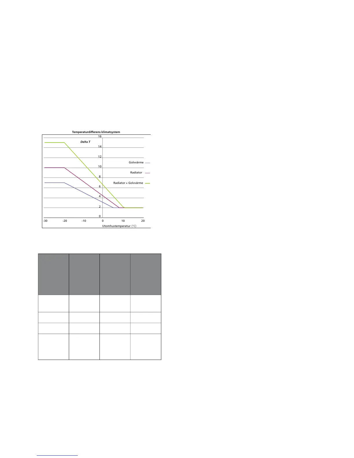
Heating
A diagram is created for a certain DOT to optimise the
energy transfer (in this case -20 °C). The diagram shows
target delta-T for three different climate systems.
General formula:
Delta = (DT-max / DOT - Stop-heating) x (BT1 - Stop-
heating)
Under floor
heating
+
Radiator
(°C)
Radiator
(°C)
Under floor
heating
(°C)
Constants
151515Stop-heat-
ing
71015DT-max
-20-20-20DUT
4 (inverters)44DT-min
7 (on/off
machines)
Determining the speed using regulator:
■
For F2040, control is locked and run at the last calcu-
lated speed whilst defrosting is initiated but no actual
defrosting has started yet.
■
During compressor operation only, BT12 and BT3 are
used in EB101 for calculation.
■
During operation with compressor and when internal
electric additional heat EB1 is activated, BT12 and
BT3 are used in EB101 for calculation. 30 % is the
minimum permitted speed when the internal electric
additional heat EB1 is active.
■
During operation with only internal electric additional
heat EB1 is used BT63 for VVM 320 and BT3 for EB101
for calculation. 30 % is the minimum permitted speed
when the internal electric additional heat EB1 is act-
ive.
■
When shifting between different demands (e.g.
heating-hot water), starting the compressor and re-
placing controlling sensors, GP1 starts at the highest
of the read-off values in the graph (Pump speed at
start) and at the speed the new demand had the last
time it was run. This applies to all demands (heating,
hot water, pool and cooling). This speed is then
locked for 2 minutes.
19Chapter 4 | Description of functionsNIBE™ VVM 320

 Loading...


