Flow settings charge pump GP1 VVM 320
This function is used to check the flow between indoor
and outdoor units. The purpose of the function is to
be able to diagnose the fault in the event of suspected
flow related problems.
Program sequence:
■
Check that BT6 is less than 40*C otherwise the text
”Drain hot water to cool Water heater” appears.
■
Sets reversing valves to HW-mode.
■
Starts GP1 and runs at maximum speed.
■
Starts the compressor.
For on/off models the following applies: if the
compressor does not start within 10 minutes, the flow
setting is cancelled and information is given stating
that the compressor could not be started.
For inverter models the following applies: if the
compressor does not start or reach 55 hz within 10
minutes, the flow setting is cancelled and provides in-
formation stating that the compressor could not be
started/reach the desired frequency.
For 1-phase inverters, the phase that the 1-phase invert-
er is connected to is detected. A message is given stat-
ing that the 1-phase inverter is being detected. When
the phase has been detected the message ”Compressor
detected on phase L?” is shown. If the compressor could
not be detected the message ”Could not detect com-
pressor phase” is shown. This function may run during
the 5 minutes that the compressor is to run before the
flow checks below are started.
■
Ensure that the compressor has run for at least 5
minutes.
■
Shows blank screen with 5 minutes countdown.
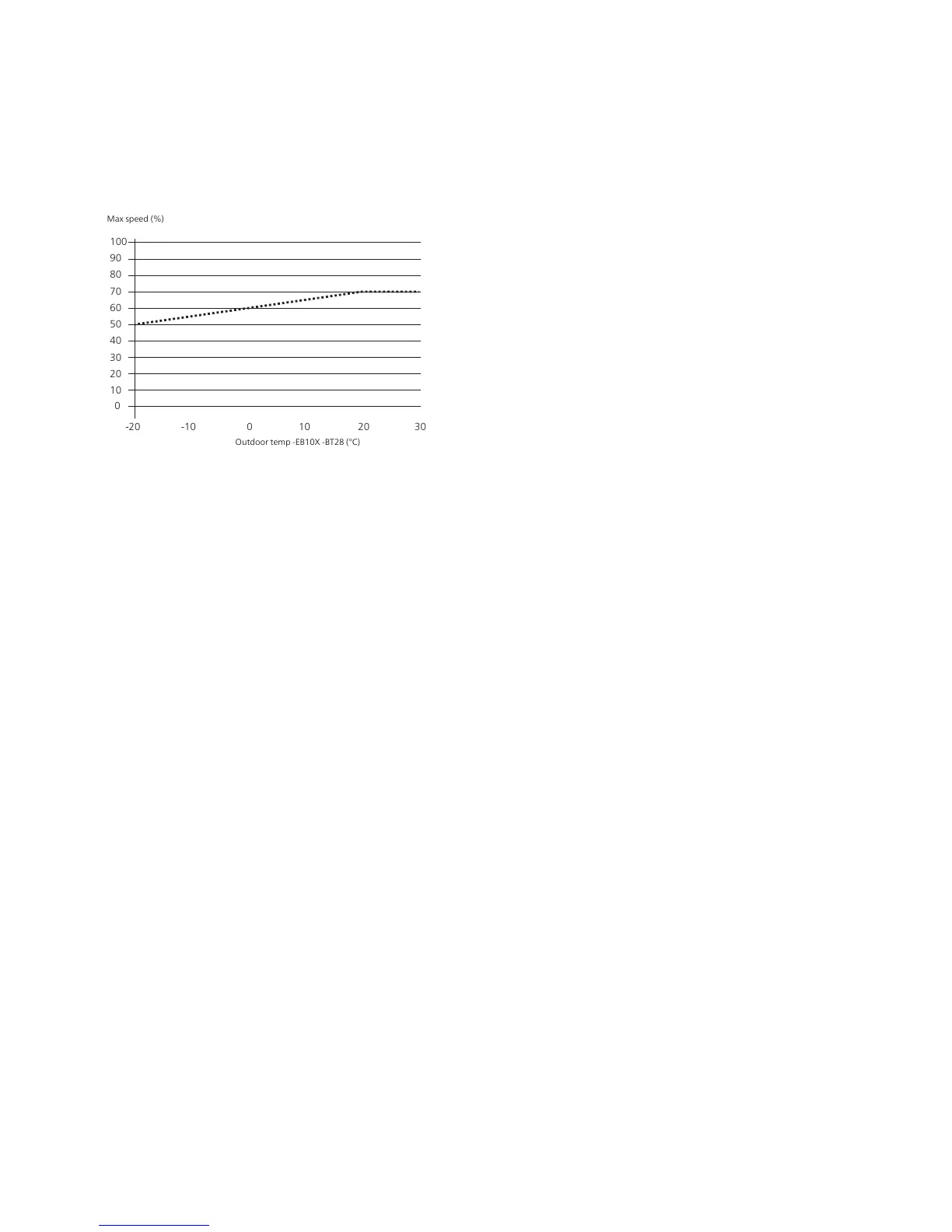
■
Shows highest recommended Δt for the given out-
door temperature.
■
Shows relevant Δt above BT12 and BT13 (the updat-
ing frequency is 10 seconds) and calculates an aver-
age value over 10 seconds.
■
The user adjusts the flow
■
Increase/Decrease the flow indicated in the display
depending on the conditions for the selected heat
pump (slave1)
■
When the condition has been met for 1 minute,
”Pump setting OK” appears.
■
When the user exits the menu, control of the charge
pump is released again and returns to the same op-
erating mode as for the setting.
Dimensioned flow for VVM 320 is 12 kW at 9 °C. It gives
a flow corresponding to 1150 litres. The coil in the
water heater can be deemed to correspond to the
pressure drop in the radiator circuit. For smaller external
parts, F2030-7 and F2040-8, 20% less flow than the
dimensioned flow is permitted.
Hot water
If hot water in menu 5.11.1.2 is set to auto, GP1 controls
according to ”Determining the speed using regulator”,
otherwise after the manually set speed.
POOL
If pool in menu 5.11.1.2 is set to auto, GP1 controls
according to ”Determining the speed using regulator”,
otherwise after the manually set speed.
Defrosting
Any control is stopped
During defrosting the speed is set to a maximum
of:
■
The average value of the speed GP1 that the com-
pressor ran to meet the heating demand of the cur-
rent defrosting/ manually set speed for the 2 last
minutes.
■
50 %
During tank defrost the speed is set to a maximum
of:
■
The average value of the speed GP1 that the com-
pressor ran to meet the heating demand of the cur-
rent defrosting/ manually set speed for the 2 last
minutes.
■
70 %
At completed defrosting:
■
If GP1 is controlled, it returns to 30 % higher speed
than it had just before defrosting. The exception is
if priority shift occurs during/in conjunction with
defrosting. This priority shift is then treated as a
normal shift.
■
If GP1 is not controlled, GP1 returns to the speed set
for respective demand according to menu 5.11.1.2.
During passive defrosting:
■
GP1 controlled according to operating mode
Auto/Intermittent in menu 5.11.1.2
If GP1 is stationary regardless of operating mode, the
pump exercising function is used.
In emergency mode, GP1 is run without PWM signal,
which means that it runs at maximum speed.
21Chapter 4 | Description of functionsNIBE™ VVM 320

 Loading...


