Connections
FunctionOutput
-K1
-K2
-K3
HWC pump GP11K4
Energy measurement kit (EMK 300)
The flow meter is installed on the supply line from
EB101 with the arrow in the direction of flow.
The temperature is measured using the installation's
existing sensor.
■
Activated in Menu 5.2-System settings.
Pool (POOL 310)
Address (dipswitch setting): 0110 0000
■
During simultaneous heating demand the priority is
determined by the settings made in menu 4.9.1.
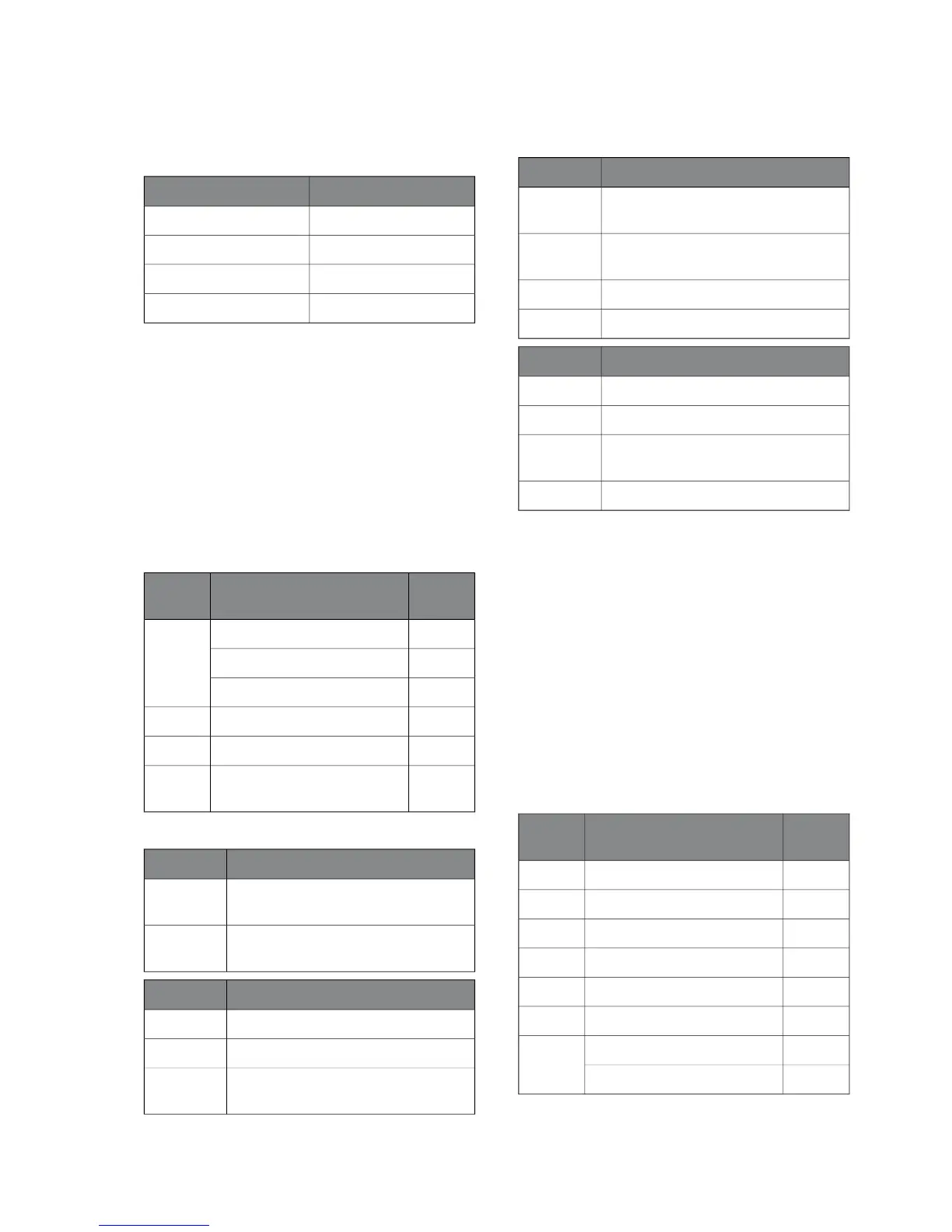
Current menus
Factory
setting
NameMenu
activated4.1.1
22 °Cstart temp
24 °Cstop temperature
op. prioritisation4.9.1
Heating medium pump speed5.1.11
Activating/deactivating of ac-
cessories
5.2
Connections, accessory card
FunctionInput
external blockingAA5-X2:21-
22
Pool sensor (BT51)AA5-X2:23-
24
FunctionOutput
Circulation pump (GP9)AA5-X9:7-8
Circulation pump (GP9)X1-3
Blue cable Reversing valve motor (QN19)
as well as circulation pump (GP14)
AA5-X9:5
FunctionOutput
Black cable Reversing valve motor (QN19)
as well as circulation pump (GP14)
AA5-X9:6
Brown cable Reversing valve motor
(QN19).
AA5-X10:2
PWM Brown cable (GP14).AA5-X2:5
PWM Blue cable (GP14).AA5-X2:6
FunctionInput
--K1
--K2
Pool reversing valve (QN19) as well as
(GP14).
K3
Pool pump (GP9)K4
Extra shunt group (ECS 40/41)
Address, climate system 2 (inst. dipswitch): 0100 0000
Address, climate system 3 (inst. dipswitch): 1100 0000
Address, climate system 4 (inst. dipswitch): 0010 0000
When heating is permitted, the shunt is controlled to
the calculated flow temperature and when cooling is
permitted the shunt is controlled to the minimum flow
temperature, in relation to supply temperature sensor
2/3/4.
The shunt valve controls the number of whole seconds
as the differential (calculated flow temperature 2/3/4
– supply temperature sensor 2/3/4) * shunt valve
amplification. The mixing valves open for even numbers
and close for odd numbers. The mixing valves are sta-
tionary during the waiting period 2/3/4.
Current menus
Factory
setting
NameMenu
0Parallel offset1.1
9heating curve1.9.1
0external adjustment 2/3/41.9.2
15 °Cmin. flow line temp.1.9.3
NoRoom sensor1.9.4
60 °CMax calculated flow5.1.2
1.0mixing valve amplifier5.3.3
30 secsmixing valve step delay
NIBE™ VVM 320Chapter 4 | Description of functions28

 Loading...


