Air/water heat pump (EB101)
EB101 with inverter controlled compressor
EB 101 always controlled using a frequency table. There
are 3 different frequency tables for heating operation
depending on climate. During hot water charging the
frequency table uses high power.
EB 101 has different maximum frequency according to
the following:
2040-162040-122040-8Model
120120118BT28 ≤ 2°C
8585812°C < BT28 ≤
18°C
856074BT28 > 18°C
Heating mode
Menu 5.1.23 Requested compressor frequency is auto:
■
There are 3 different standard folders depending on
climate. The different models of EB 101 are thought
to cover a peak output demand according to the
following:
2040-162040-122040-8Model
16 kW12 kW8 kWMax output
requirement
at DOT
■
DOT already controls the circulation pumps. The same
DOT is used here to determine which folder is to be
used.
-15 °C-6 °C - -
15 °C
-6 °CDUT
-20 climate-12 climate-4 climateFolder
Hot water operation
Menu 5.1.23 Requested compressor frequency hot
water is auto:
■
Uses folder high output.
Pool
Menu 5.1.23 Requested compressor frequency pool is
auto:
■
Uses folder high output.
Cooling mode
Menu 5.1.23 Requested compressor frequency cooling
is auto:
■
EB 101 runs at min speed.
Defrosting inverter controlled compressor
When EB 101 initiates defrosting, control is follows:
Defrosting first starts after EB 101 has initiated defrost-
ing for longer than 40 seconds.
Defrosting to water heater
If there is insufficient energy in the heating system,
defrosting occurs to water heater.
Defrosting to water heater is performed in follow-
ing cases:
■
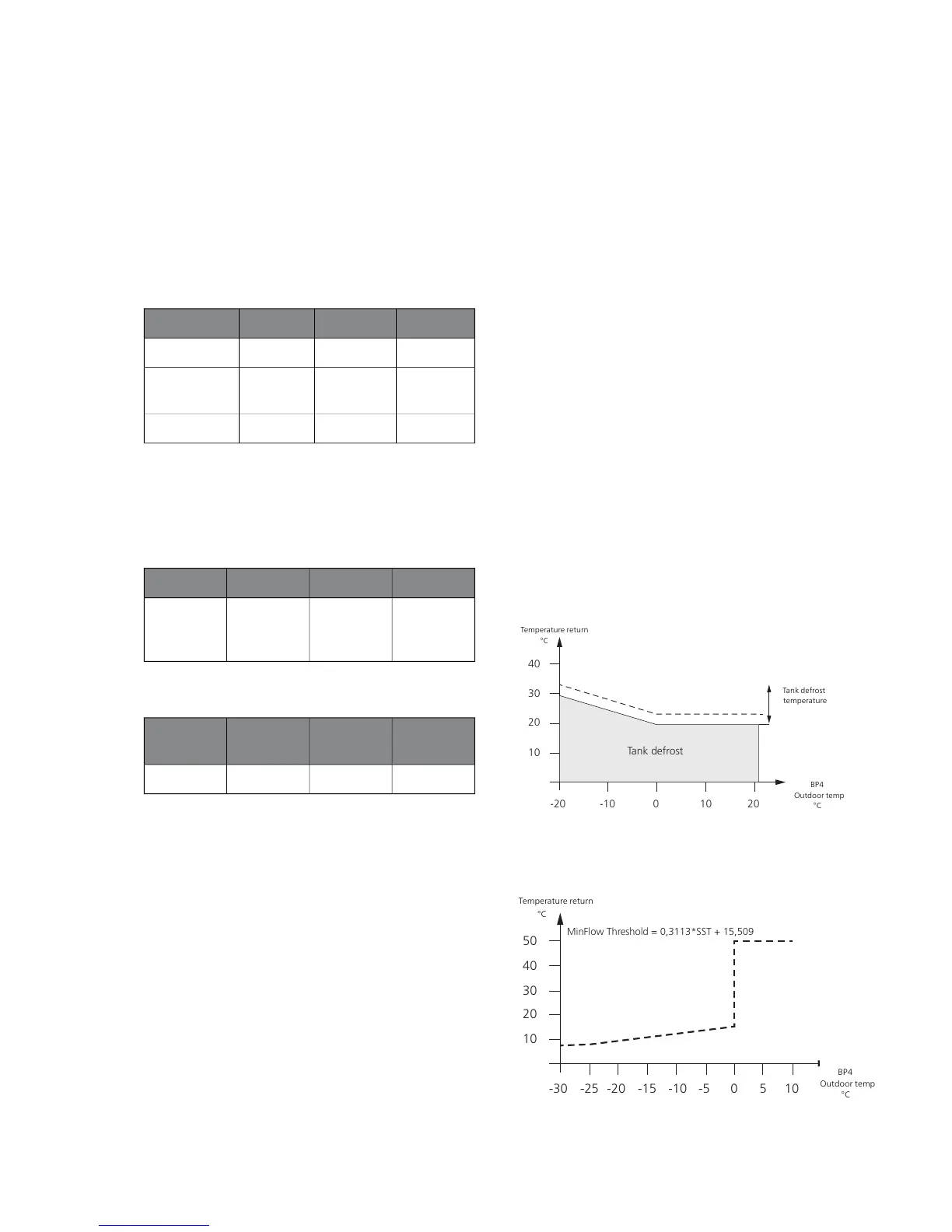
Return temperature BT3 is less than TankDefrostTemp
(see diagram below).
■
The temperature of BT12 is less than 10 °C.
■
The value on BP4 is greater than MinFlowThreshold
(see diagram below).
■
Heating is blocked.
If any of the following occurs for longer than 40
seconds, during defrosting to the system, defrosting
occurs to the water heater:
■
The temperature of BT12 is less than 10 °C.
■
BP4 (F2040) is greater than MinFlowThreshold.
If the value of BT6 is less than TankDefrostTemp
must be:
■
Hot water prioritised until TankDefrostTemp achieved,
i.e. QN10 is towards hot water and additional heat
(EB1) is used for TankDefrostTemp + 5 °C has been
reached.
After completed defrosting the compressor resumes
to meet the demands it made before defrosting.
Conditions for tank defrosting depending on the value for -BT3

 Loading...


