18
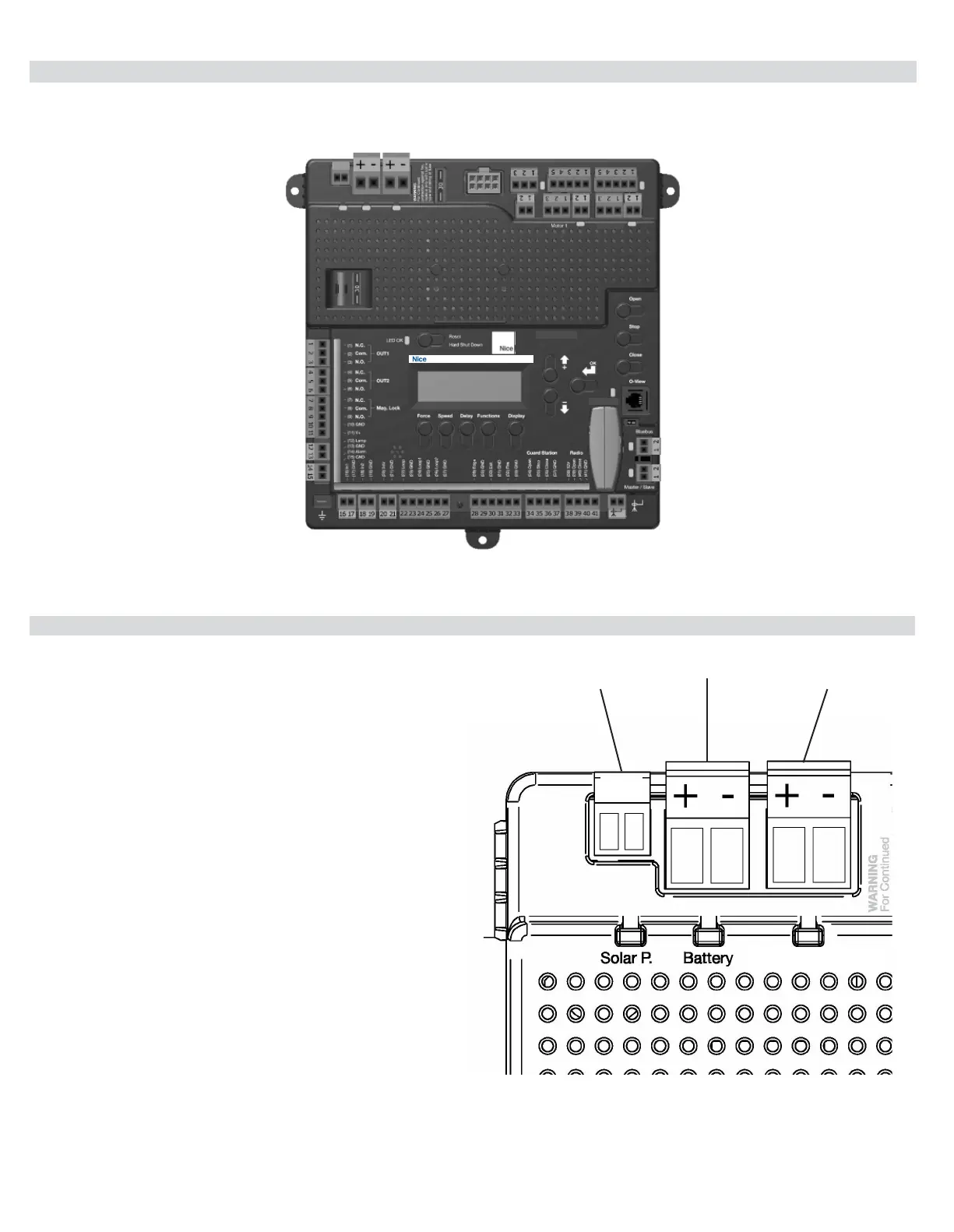
12 - INCOMING POWER WIRING
Power input connections should be wired as follows:
Solar panel
Connect wires to the solar panel terminal block. The positive
wire of the panel connects to the left terminal marked “+”.
Note: If the panel is connected backwards a red LED will
illuminate below the terminal. If solar power is to be used it
will be necessary to program control board for STANDBY
operation. See section 16 for information on STANDBY
mode.
Battery
Connect wires to the battery terminal block. The positive wire
of the battery connects to the left terminal marked “+”. Note:
If the battery is connected backwards a red LED will illuminate
below the terminal.
Main DC Power - This terminal block is for incoming 10-
32VDC power only!
Connect wires to the main DC power terminal block. Positive
of the power supply connects to the left terminal marked “+”.
Note: If supply is connected backwards a red LED will
illuminate below the terminal. If supply is connected properly a
green LED will illuminate. See 120VAC wiring section for more
options.
SOLAR
PANEL
BATTERY
MAIN DC
POWER
+ -
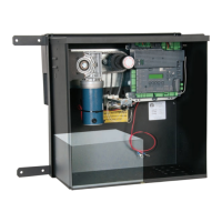
11 - CIRCUIT BOARD LAYOUT
+
-
MAIN DC POWER 30A FUSE MOTOR
SERIES 1050
MOTOR 2
BATTERYSOLAR P.
OXI/A Receiver
UL325 Compliant Monitored Safety Devices(s) required.
Accessory
Output
Connections
Power Input
Connections
Motor Output
Connections
BlueBus
Connection
Master / Slave
Connection
Accessory Input Connections
Earth Ground
Note: Main DC Power input is typically only used on our
commercial operators. No connection is required on the
7251/7351 system.
MAIN DC POWER