20
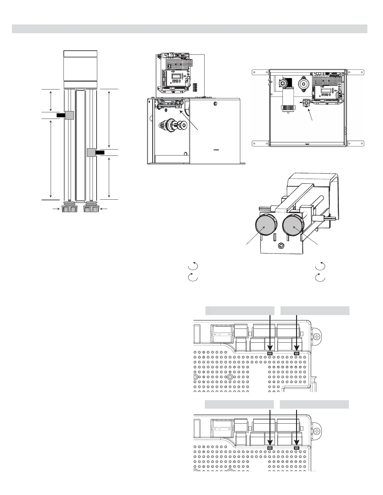
13.2 - SETTING THE LIMIT SWITCHES
OPEN LIMIT
Green OPEN LED
1. Using the OPEN button on the front of the Control Board,
hold the button down until the gate reaches the fully
intended open position.
2. Adjust the Open Limit on the operator until the GREEN
light illuminates on the front of the control board as shown
above. The fully OPEN limit switch is now set.
Note: If red LED illuminates, reverse orange and white limit
wires
MOTOR 1 LED - GREEN MOTOR 2 LED - GREEN
CLOSE LIMIT
Red CLOSE LED
3. Using the CLOSE button on the front of the Control
Board, hold the button down until the gate reaches the
fully intended closed position.
4. Adjust the Closed Limit on the operator until the RED light
illuminates on the front of the control board as shown
above. The fully CLOSED limit switch is now set.
MOTOR 1 LED - RED MOTOR 2 LED - RED
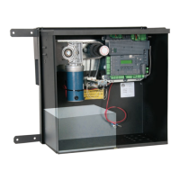
The limit adjustments are located inside the control box between
the circuit board and motor assembly as shown.
Increase
travel for
movement to
the left
Decrease
travel for
movement to
the left
Increase
travel for
movement to
the right
Decrease
travel for
movement to
the right
Limit adjustment
knob for left
movement
Limit adjustment
knob for right
movement
Limit adjustment knob
for left movement
- Increase travel
- Decrease travel
Limit adjustment knob
for right movement
- Decrease travel
- Increase travel
Limit adjustment
assembly
NOTE: The control board is already in the “LEARN
MODE” when shipped. You are in LEARN MODE if the
word “ENTER” is ashing below “LEARN”.
If the board is not in “LEARN MODE”, press:
FUNCTION OK SWING OK LIGHT OK
AVERAGE
HEAVY
You are in LEARN MODE if “ENTER” is ashing.
For dual gate installations - set one motor at a time.
Limit adjustment
assembly