24
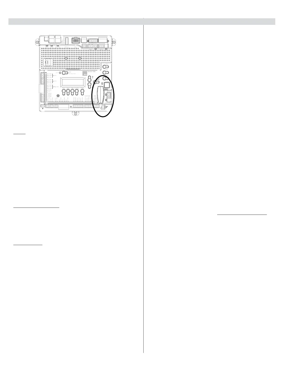
15.3 - Communication buses 15.4 - Programming the plug-in receiver and remote controls
Nice Plug in Receiver: The Nice OXI/A Plug-In Receiver provides up to
15 channels for specic control of individual gate functions. The receiver
includes built-in programming functions for adding or removing Nice wireless
remote controls to/from a gate installation. The following procedures detail
the steps to assign a remote control, add a new remote control, delete
a single remote control, or remove all remote controls from the receiver
memory.
Programming the Nice 2-Button or 4-Button Remote Control with the
Nice Plug-In Receiver.
These procedures apply to the Nice wireless remote control. These
procedures assign factory default controls automatically to the remote
control.
1. Have a functioning Nice 2-button or 4-button remote control with a
battery installed prior to programming the remote control.
2. Press and hold the button on the side of the Nice receiver until the led
illuminates green on the Nice receiver, then release the button.
3. Within 10 seconds, press and hold any key on the Nice remote control
until the led in the Nice receiver blinks green 3 times, indicating that the
Nice remote is programmed to control the receiver.
4. After the led on the Nice receiver blinks green 3 times, another 10 second
interval is started to program another Nice remote control if desired.
Repeat step 3 to program the additional Nice remote control (transmitter).
Step 3 may be repeated as many times as necessary to program all
available Nice remote controls.
5. Verify that the Nice remote control(s) can control the gate by pressing one
or more buttons individually on the remote control(s).
Add new remote control to the Nice Plug-In Receiver
A Nice remote control that has been programmed to control a Nice receiver
may be used to create other Nice remote controls for the same receiver. This
procedure needs to be performed within 10 to 20m (30 to 60 feet) of the
Nice receiver, but the Nice receiver does not need to be physically accessed.
1. Press and hold any button on the non programmed Nice remote control
for at least 5 seconds, then release the button, taking note of the button
that was pressed.
2. Press the same button on the programmed Nice remote control three
times.
3. Press the same button in step 1 on the non programmed Nice remote
control and release.
4. It is recommended to test the new copy of the Nice remote control with
the assigned gate controller.
NOTE: This procedure will affect all Nice receivers within radio
range.
Deleting a Single Nice Remote Control from the Nice Plug-In
Receiver Memory
A Nice remote control that has been programmed to control a Nice receiver
may be removed from the Nice receiver memory without affecting other
assigned remote controls. This procedure needs to be performed at the Nice
Plug-In Receiver with the affected Nice remote control.
1. Press and hold the button on the side of the Nice receiver until the led on
the Nice receiver illuminates green and keep the button pressed. The led
will illuminate after approximately 4 seconds.
2. Press and hold any button on the Nice remote control until the led on the
Nice receiver blinks 5 green ashes
3. Release the button on the side of the Nice receiver.
4. It is recommended to verify that the non programmed Nice remote control
no longer controls the gate.
Figure - COMMUNICATION BUSES
OVIEW
Programming and diagnostic unit which connects directly to the gate
controller and is part of the Nice “Opera” control system. The unit can be
used in “stand-alone” mode via its front-panel keypad, or it may be accessed
via a Bluetooth-enabled PDA, or PC when used with the O-View Software
Suite. This unit, when matched with the OVIEW Bluetooth enables remote
control and management of the gate controller. Remote control functions
include most of the programming functions that are available at the front
panel LCD on the control board as well as software updates.
OVBT: Bluetooth module for OVIEW and the “O-View Software Suite”
application for PC, PDA, or Smartphone for localized wireless control of the
gate controller.
O-VIEW Software Suite: Provides desktop or Smartphone level control of
the gate controller. Other benets include software updates that can be made
as new versions of software are made available.
BLUEBUS ACCESSORIES
ERA Series Photo Eyes: Photocell transmitter and receiver pair that
connects to the 2-wire BlueBUS connector with unshielded twisted-pair wire
and is a non-contact sensor for entrapment protection as specied in UL325,
Section 31.1 “General Entrapment Protection Provisions”. Up to six pairs of
eyes may be connected.
MASTER/SLAVE - ONLY USED IN 24V COMMERCIAL OPERATORS
The gate operator includes a two-pin connector designed to link two
separate gate operators together as a Master/Slave pair. The Master/Slave
conguration is enabled by connecting two gate operators with simple,
unshielded twisted-pair wire (Max.100 ft.). All entrapment sensors, switch
inputs, receiver controls, and outputs must be wired to the gate operator
designated as the “Master”. The following procedure outlines the process for
conguring the Master/Slave pair.
Perform the “Learn” process to congure open and close limits with the gate
for each operator. See the “Programming Quick Start” procedures in this
manual for a description of the gate learning process.
On the Master operator, select Function -> Adv. Settings -> Remote Mst. Slv.
Then select On -> Master. The red LED associated with the Master/Slave
connector will illuminate.
On the Slave operator, select Function -> Adv. Settings -> Remote Mst. Slv.
Then select On -> Slave. The red LED associated with the Master/Slave
connector will illuminate.
The Master/Slave pair is now congured. The Slave gate operator will
perform identical open/close/stop functions in tandem with the Master gate
operator.
Safety
Shadow
Entrap
Shadow
15 - ACCESSORY INPUTS AND OUTPUTS (CONT.)