English–3
English
with gate on the left
mm
50
100
with gate on the right
150
50
mm
02. Installtherackanddenethepositionofthefoundationplate(Fig.4).
4
> 40 cm
03. Digthefoundationandarrangethetubesfortheelectricalcables.
04. Inserttheanchorboltsintothefoundationplateandfastenthemwith
onenutbelowandoneabovetheplate,sothatthethreadedpart
andtheboltprotrudebyroughly35–40mmabovetheplate(Fig.5).
5
35÷40 mm
x 2
05. Insertthetubesfortheelectricalcablesthroughtheopeningofthe
plate(Fig.6).
06. Insert the anchor bolts into the cement previously cast into the
foundation hole. Level the plate properly and ensure that the
engraved side indicating the position of the pinion faces the gate,
alignedaccordingtothemeasurementsshownabove.
6
40 mm
40 mm
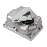
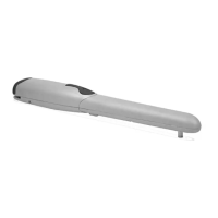
07. Oncethecementdries,removethetwonutsfromtheanchorbolts
andpositiontheautomationonthefoundationplate(itmustlieparal-
leltothegate)thensecureitwiththetwowashersandnuts(Fig.7).
7
3.2 - POSITIONING THE RACK
01. Unlockthegearmotormanually,openthegatecompletely(Fig.8)and
installtherstsegmentoftherack(Fig.9).Fastentherackalongits
entirelength,whilemakingsurethatthereisaspaceofatleast1and
2mmbetweenthepinionandtherack(Fig.10).
02. After installing the last part of the rack, cut away the excess part
(Fig.11).
03. Itmustnotgobeyondthegate(Fig.11).
1÷2 mm
109 11
8
 Loading...