4–English
English
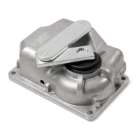
3.1 - INSTALLING THE LIMIT SWITCHES
01. Position,approximately,thetwolimitswitchbrackets[A]ontherack
(Fig.12).
02. Movethegatebyhandtotheopenposition,stoppingitatleast2–3
cmbeforethemechanical stop;whilemovingthegate,makesure
thattherackslidessmoothlyonthepinion.
03. Slidethelimitswitchbracketalongtherackintheopeningdirection
untilthelimitswitchtrips.Next,movethebracketatleast2cmfurther
andthenlockitontotherackwiththegrubscrewsprovided.
04. Repeatthesameoperationtofastentheclosedpositionlimitswitch.
A
216
33
90
12
3.4 - ELECTRICAL CONNECTIONS
Maketheelectricalconnectionsforthevariouselementsaccordingtothefollowingdiagram(Fig.13).
The connections must be made in no-voltage conditions.
NC
TX RX
NO
Fuse 1A T
Flash
ECSbus
Stop
Aerial
SbS
OGI
Fuse 15A
L4 L3 L2
SbS
L1
led Stop
led SbS
led ECS
(B)
(A)
(C)
230 V, 500 W max
(D)
A
LM100(optional)
B Additionalsafetyelement.There’snouseconnectingitifitwillnotbeused.
C Contactforconnectinganintercomorvideointercomonlyifthesedeviceshavea“dry”contactoutput.
D Lampconnection(NotpresentinversionAU01).
13
 Loading...