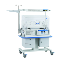
OPERATOR’S MANUAL FOR INFANT INCUBATOR EDITION/REVISION B/0
2-2
I4-1
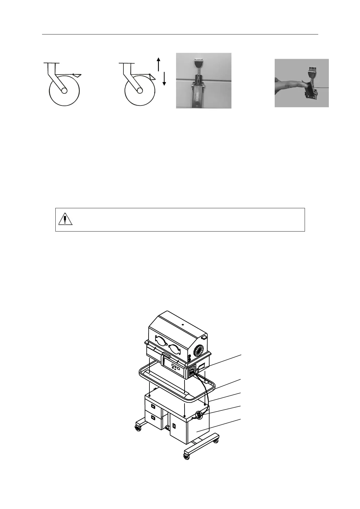
(Enlarged figure I) (Enlarged figure II)
2 Main body of Incubator
1
Cabinet
wheel unlocked wheel locked hang on the lock close the lock
spanner
NOTE: See Enlarged figure I, lock the casters as the arrow 1 indicates, and unlock the
casters as the arrow 2 indicates.
See Enlarged figure II, hang on the lock , and close the lock spanner.
IMPORTANT: Be careful not to install the guard rail in wrong direction, or else, the
controller can not be taken out. The front access panel and the cabinet door
should be in the same direction.
The guard rail ensure grounding through bolt,therefore, fixing the guard
railon the cabinet with bolts.
FIGURE 2.2
B. Install the main body onto the Vertical Height Adjustment Stand
a. The method of installlation casters is same as part A.
b. The method of installlation main body, guard rail on the Vertical Height Adjustment cabinet
samw as part A.
c. After installation, insert the power cord on the right side of Vertical Height Adjustment
cabinet into the power socket in figure 4.2.
Main body of Incubator
Guard Rail
Power cord
Lock
Cabinet
FIGURE 2.3


 To Next Page