4-1
I4-1
OPERATOR’S MANUAL FOR INFANT INCUBATOR EDITION/REVISION B/0
SECTION 4
OPERATION
4.1 GENERAL
This section provides operation procedures for Infant Incubator.
4.2 POWER SUPPLY CONNECTION AND SWITCH CONTROL
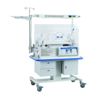
See figure 4.1, for the infant incubator with VHA cabinet, general power socket and the
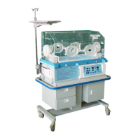
general power switch are located under the cabinet; See figure 4.2, for the infant cubator with
fixed cabinet, general Power supply socket and general power switch, auxiliary mains output
socket are located on the back of controller.
General power switch
General power socket
FIGURE 4.1
Data communication connector
Socket for skin temperature sensor
Power switch
Auxiliary mains output socket
(To phototherapy)
Power supply socket
FIGURE 4.2
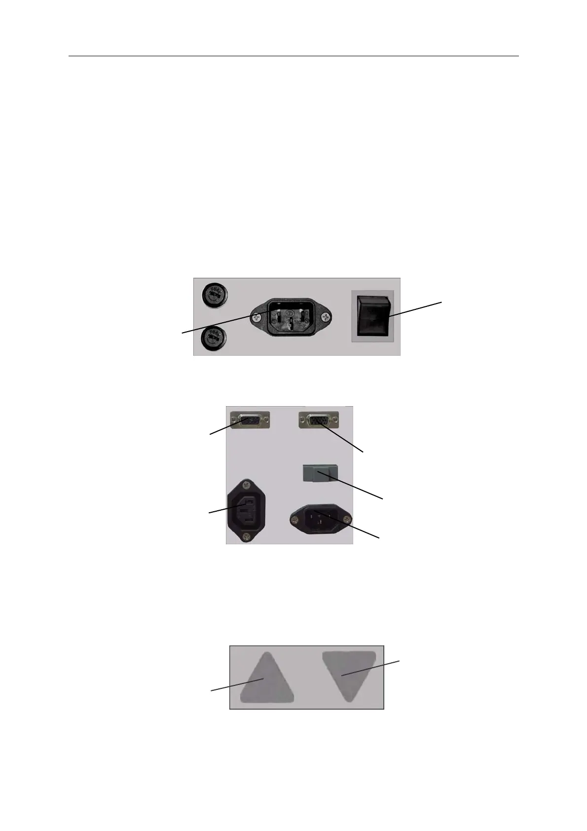
See figure 4.3, for the infant incubator with VHA cabinet, the height adjustment foot button is
on the bottom of stand.
Down foot button
Up foot button
FIGURE 4.3
CAUTION: The vertical height adjustment Stand should be restarted after 30s.
 Loading...