After Sales
Technical Documentation
RAE/RAK–1N
UIF
Page 4– 6
Amendment 1 04/97
The major parts on the module assembly include the following:
– CMT Display module. Same module as used in HD841 including LCD,
Heat seal, LCD driver TAB circuit and Light guide.
– CMT keydome assembly: Adhesive film holding 20 metal domes.
– Soft keys on the other side of PCB: four domes on the other end and
two domes on the other end.
– 33–pin flex connector for hinge flex.
– 12–pin flex connector for GK1 display module.
– Coaxial cable connector for antenna cable.
– Antenna clips.
– 11 test pads.
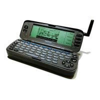
Figure 2. shows the UIF mechanical shape and part placement.
PDA scroll keys
CMT Keypad
Testpads
CMT LCD foil pattern
Hinge flex connectorPDALCD flex connector
PDA softkeys
Antenna circuit
LEDs
Figure 2. UIF Board
Note: For RAK –1 (GK2_1module) the antenna
circuit is different from the one shown in this dia-
gram. See the UIF Component Layout in section
10 for details.
UIF Flexes
There is two flexes that are connected to the UIF module and go through
the hinge. The other one is 33–pin flex. It has all active signals for the UIF
module and three ground pins. It is connected to the 33–pin flex
connector. The other one has one wide ground line. It is connected by
using two sided copper tape with conducting adhesive. It is needed to
improve EMC characteristics.

 Loading...