1
2
3
V24/CTI PC
V24/CTI
Interface Module
Wall Socket
(to the PCX)
UA line
or
CTI
V24
9 Series Set
(Optional)
UA line
Figure 8.8: V24/CTI Interface Module Connection
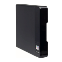
The V24/CTI Interface Module is connected to:
1. The digital set 3 m maximum length ( RJ11/RJ11 cable)
2. The PCX via a wall socket and a distributor frame
3. The CTI or V24 terminal:
• V24: 3m maximum length
• CTI: 3m maximum length
8.7.3.2 V24/CTI Interface Module Rear Panel Details
UA
1
2 3
Figure 8.9: Rear Panel
1. RJ11 connector for UA line to PCX
2. V24 SUBD9 connector
3. CTI SUBD9 connector
Chapter
8
Device commissioning
8AL91217USAA - Ed. 01 - July 2018 - Installation Manual 144/216

 Loading...