Nokia WiFi Gateway 3 Product Guide Gateway 3 (G-240W-E) unit data sheet
Issue: 01 3FE-47464-AAAA-TCZZA 41
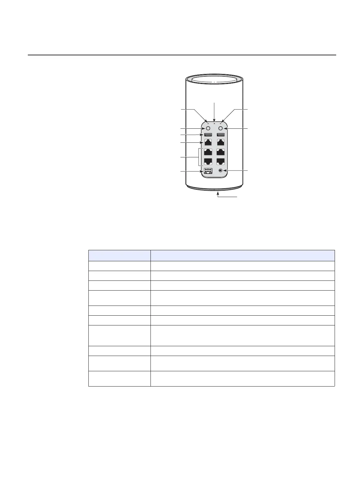
Figure 7 Gateway 3 (G-240W-E) physical connections
Table 8 describes the physical connections for Gateway 3 (G-240W-E) devices.
Table 8 Gateway 3 (G-240W-E) physical connection
Connection Description
GPON LED This LED is used to show the start of the GPON uplink.
VOIP LED This LED is used to show the start of VOIP services.
On/Off button This button powers the unit on or off.
WPS ON/Off button This button is used to power the WiFi Protected Setup (WPS) of new WiFi devices
on or off.
USB 1 and USB 2 This connection is provided through two USB 2.0 interfaces.
TEL1 and TEL2 This connection is provided through two RJ-11 POTS ports.
LAN 1 to LAN 4 This connection is provided through Ethernet RJ-45 connectors. Up to four
10/100/1000 Base-T Ethernet interfaces are supported. The Ethernet ports can
support both data and in-band video services on all four interfaces.
UPS This connection is a reserved interface provided through a UPS cable.
Reset button Pressing the Reset button for less than 10 seconds reboots the device; pressing
the Reset button for 10 seconds resets the device to the factory defaults.
Power input This connection is provided through the power connector. A power cable fitted with
a barrel connector is used to make the connection.
ON/OFF
RESETGPON VOIP
WPS
LAN 1 LAN 2
LAN 3
POWERUPS
LAN 4
TEL 1 TEL 2
USB 1 USB 2
Power input
Bottom cover
Wi-Fi security button
VOIP LEDGPON LED
Reset
button
On/off button
USB ports (2)
POTS ports (2) RJ-11
Ethernet ports (4) RJ-45
UPS connector
28281