26
6.2 PASSIVE ROLL SYSTEMS
The following is a checklist for troubleshooting Passive Roll systems.
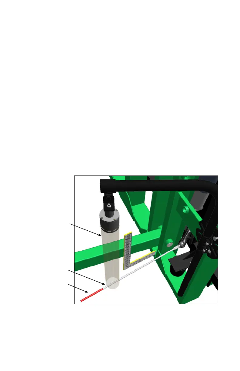
Ensure the rod is mounted perpendicular (90) to the sensor.
- if the sensor is straight vertical, the rod must be horizontal
(Figure 5)
Distance from the sensor to the target should be 20 ( 2) inches (Figure
5).
The target rod should cross the sensor’s central axis. The sensor
alignment tube (Figure 3) will help make these adjustments.
Ensure none of the parts collide with any part of the machine during
folding or operation.
- if desired, the Passive Roll rod may be trimmed, but no shorter
than 2 inches past the center of the sensor.
Ensure the adjustable target mount is tight to prevent rotation.
Ensure the sensor cable does not pull tight during operation or folding,
causing the sensor to be pulled out of alignment.
Figure 3 – Sensor Alignment Tube
Sensor Alignment
Tube
Target Rod
Cut Rod Portion
(2" Past Alignment Tube)