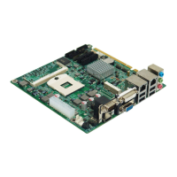
MITX-6922 Mini-ITX Motherboard Based on Intel QM67/QM77 Chipset
23
1)System power LED pins(Pin 1、Pin 2 PWRLED)
Connect system power LED cable with these pins.(pin 1 is LED anode)When system is power
on, power LED is on;when system is power off, power LED is off.
2)HD LED Pins(Pin 3、Pin 4 HDD LED)
Usually there is an HD device running status indicator on the chassis panel. When HD reads
and writes, the indicator flashes, indicating that the HD device is in operation. Connect the
cable of the HD running status indicator on the chassis panel to this connector (Pin 4 is LED
cathode).
3)Buzzer Pins(Pin 5、Pin 6 SPEAKER)
External Pin for Speaker
4)Reset Button Pins(Pin 7、Pin 8 RESET)
Connect the reset button cable to these two pins. When system fails, reset button can make the
system restart to work and no need to turn on / off the power.
5)Power ON/OFF Pins(Pin 9、Pin 10 POWER BUTTON)
Connect these two pins to the bounce switch on the chassis to connect or disconnect the power
supply.
2.5.12 Memory Slot(DIMM)
Board with 2x DDRⅢ SO-DIMM slot,support DDRⅢ/DDRIIIL 1 1066/1333/1600,memory
up to 8GB.
2.5.13 MINI PCIe Interface(MINI PCIe1,MINI PCIe2)
The motherboard provides 2x MINI PCIe slots. Users can expand Mini PCIe devices according
to their own needs. If you use MINI PCIe wireless network card, you can display the status of
wireless network card according to the selected wireless network. (the MINI PCIe2 interface
supports the SSD card functions of the standard MINI PCIe interface and EPC / mSATA
interface. Note that only one of two functions can be selected.