Hardware description
Part GPIO GPIO alternative Solder bridge
Button 1 P0.11 P1.07 -
Button 2 P0.12 P1.08 -
Button 3 P0.24 -
Button 4 P0.25 -
LED 1 P0.13 SB5
LED 2 P0.14 SB6
LED 3 P0.15 SB7
LED 4 P0.16 SB8
Table 4: Button and LED connection
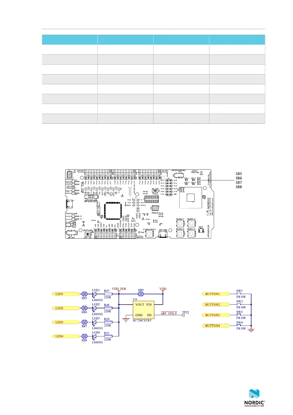
If P0.13–P0.16 are needed elsewhere, the LEDs can be disconnected by cutting the short on SB5–SB8, see
figure Figure 21: Disconnecting the LEDs on page 30. Since P0.11 and P0.12 are used as a part of the
Trace functionality, Button 1 and Button 2 can be moved to alternative GPIOs, see chapter Debug input
and trace on page 31 for more information.
Figure 21: Disconnecting the LEDs
The buttons are active low, meaning that the input will be connected to ground when the button is
activated. The buttons have no external pull-up resistor, and therefore, to use the buttons, the pins P0.11,
P0.12, P0.24, and P0.25 must be configured as input with an internal pull-up resistor.
The LEDs are active low, meaning that writing a logical zero ('0') to the output pin will illuminate the LED.
Figure 22: Button and LED configuration
4452_198 v1.0.1
30
 Loading...
