Hardware description
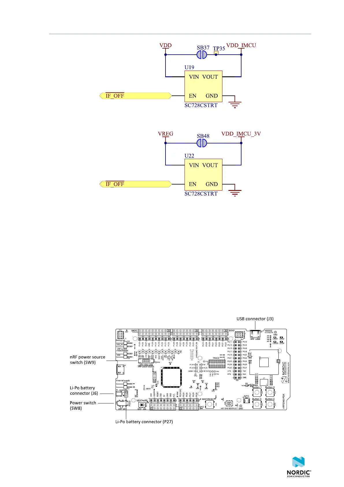
Figure 11: Interface MCU power switch
These switches are controlled by the presence of a USB connected to the interface MCU USB connector
(J2), and the state of the nRF only switch (SW6). See section Operating modes on page 19 for more
information.
5.3.4 nRF5340 power source
The nRF5340 PDK board has a power source switch (SW9) for selecting between three power sources for
the nRF5340 SoC.
The three positions of the switch are:
• VDD (default)
• Li-Po
• USB
Figure 12: nRF5340 power source switch
4406_489 v1.0
17

 Loading...
