Hardware description
Part GPIO Solder bridge
Button 1 P0.23 -
Button 2 P0.24 -
Button 3 P0.08 -
Button 4 P0.09 -
LED 1 P0.28 SB5
LED 2 P0.29 SB6
LED 3 P0.30 SB7
LED 4 P0.31 SB8
Table 6: Button and LED connection
If P0.28–P0.31 are needed elsewhere, the LEDs can be disconnected by cutting the short on SB5–SB8, see
figure Figure 22: Disconnecting the LEDs on page 25.
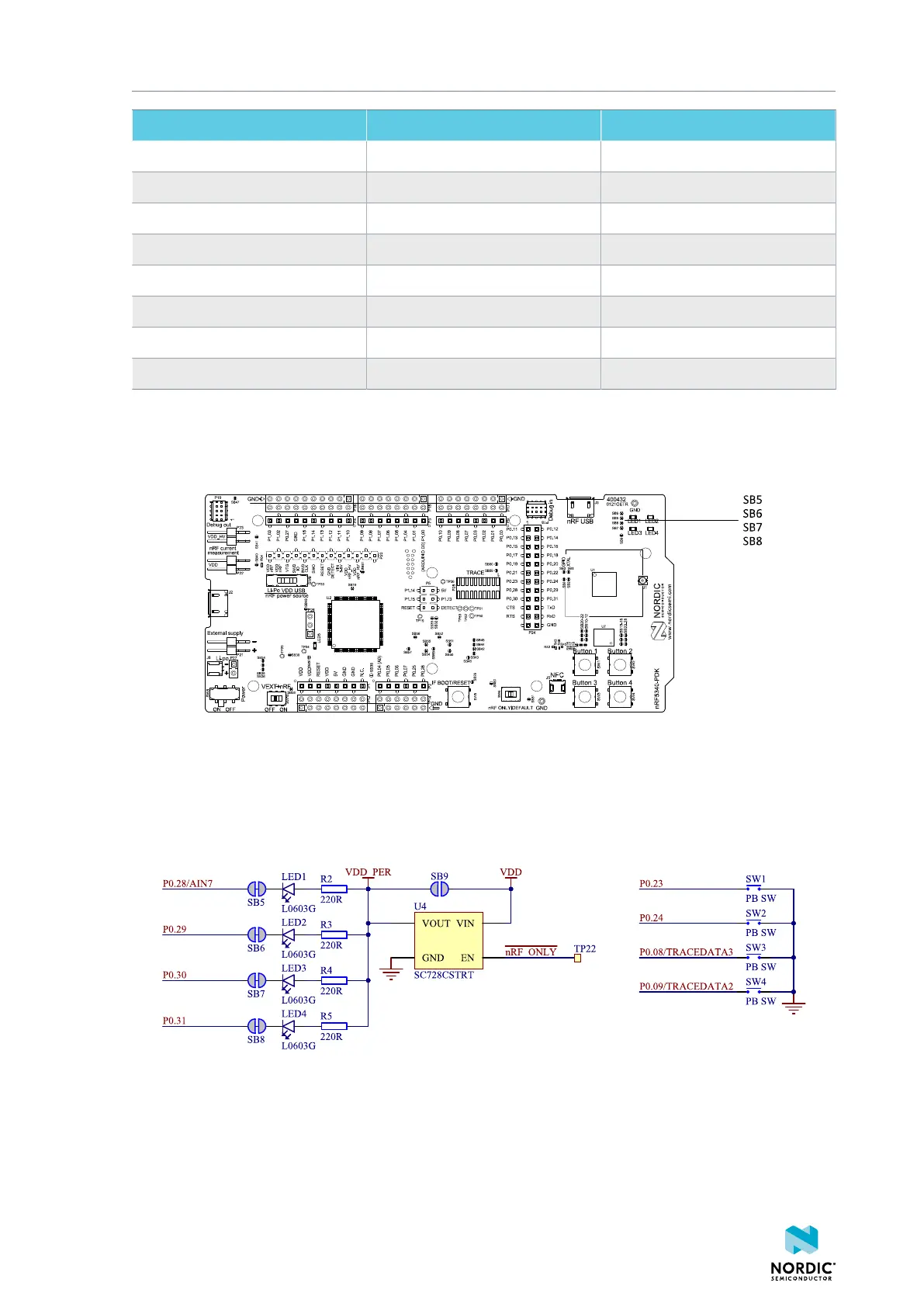
Figure 22: Disconnecting the LEDs
The buttons are active low, meaning that the input will be connected to ground when the button is
activated. The buttons have no external pull-up resistor, and therefore, to use the buttons, the P0.08,
P0.09, P0.23, P0.24 pins must be configured as an input with an internal pull-up resistor.
The LEDs are active low, meaning that writing a logical zero ('0') to the output pin will illuminate the LED.
Figure 23: Button and LED configuration
5.8 32.768 kHz crystal
The nRF5340 SoC can use an optional 32.768 kHz crystal (X2) for higher accuracy and lower average power
consumption.
4406_489 v1.0
25

 Loading...
