6
Measuring current
The current drawn by the nRF5340 SoC can be monitored on the nRF5340 PDK board.
Current can be measured using various test instruments. Examples of test equipment are the following:
• Power analyzer
• Oscilloscope
• Ampere-meter
• Power Profiler Kit
Power analyzer and Power Profiler Kit measurements will not be described in the present document. For
more information on Power Profiler Kit, see Power Profiler Kit User Guide.
For instructions for measuring, see sections Using an oscilloscope for current profile measurement on
page 33 and Using an ampere-meter for current measurement on page 34.
The nRF5340 SoC has two possible power supplies, VDD (1.7–3.6 V) and VDDH (2.5–5.5 V). The nRF5340
PDK is prepared for measuring current on both domains. Only the VDD domain current measurement
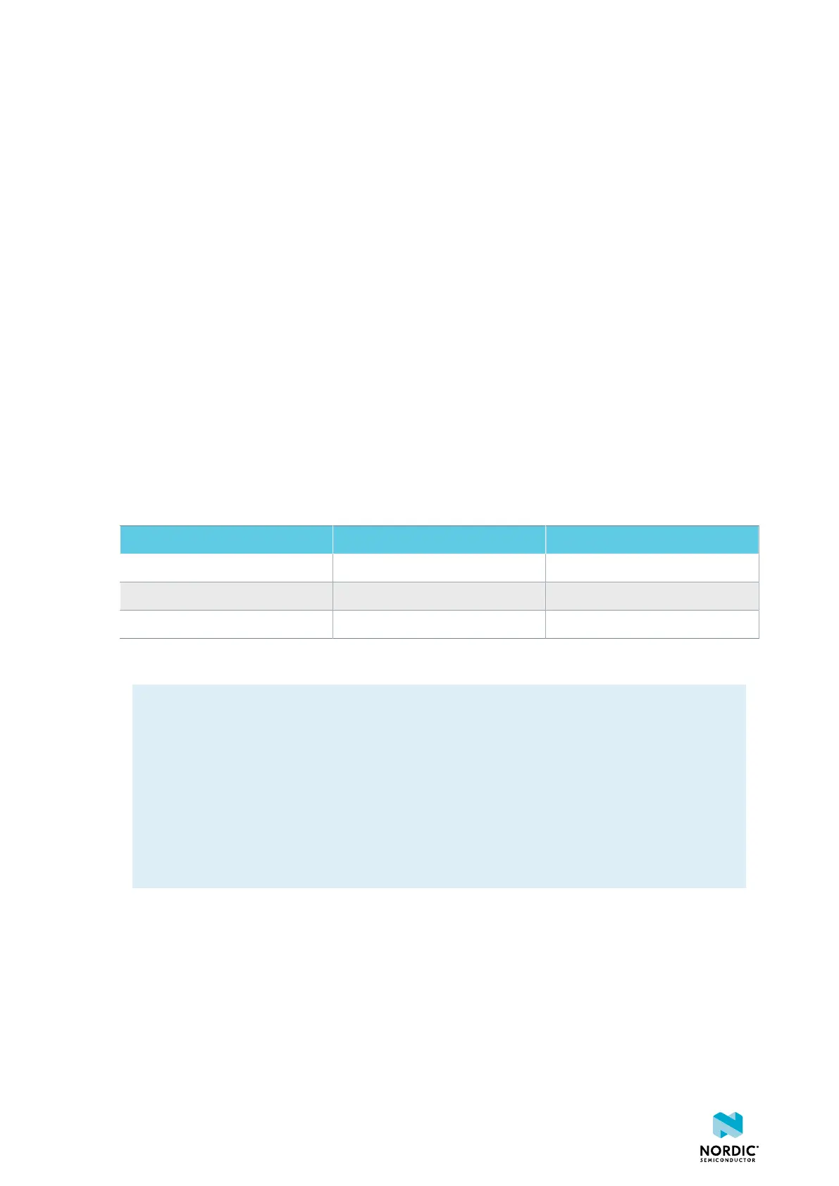
is described here, but the approach is the same with the VDDH supply. See the following table for the
corresponding components:
Component VDD VDDH
Measurement connector P22 P23
Solder bridge SB40 SB41
Series resistor R64 R67
Table 9: Components for current measurement on VDD and VDDH
Note: When measuring the current consumption:
• It is not recommended to use a USB connector to power the board during current
measurements. However, when measuring current on an application using the USB interface
of the nRF5340 SoC, the USB must be connected. It is recommended to power the board from
a coin cell battery, external power supply on connector P21 (1.7–3.6 V), or through the Li-Po
connector J6 or P27 (2.5–5.0 V).
• The current measurements will become unreliable when a serial terminal is connected to the
virtual COM port.
• After programming the nRF5340 SoC, the USB for the interface MCU must be disconnected.
For more information on current measurement, see the tutorial Current measurement guide:
Introduction.
6.1 Preparing the PDK board
To measure current, you must first prepare the board.
The suggested configurations actually split the power domains for the nRF5340 SoC and the rest of the
board.
4406_489 v1.0
32

 Loading...
