Hardware description
Figure 16: nRF only switch (SW6)
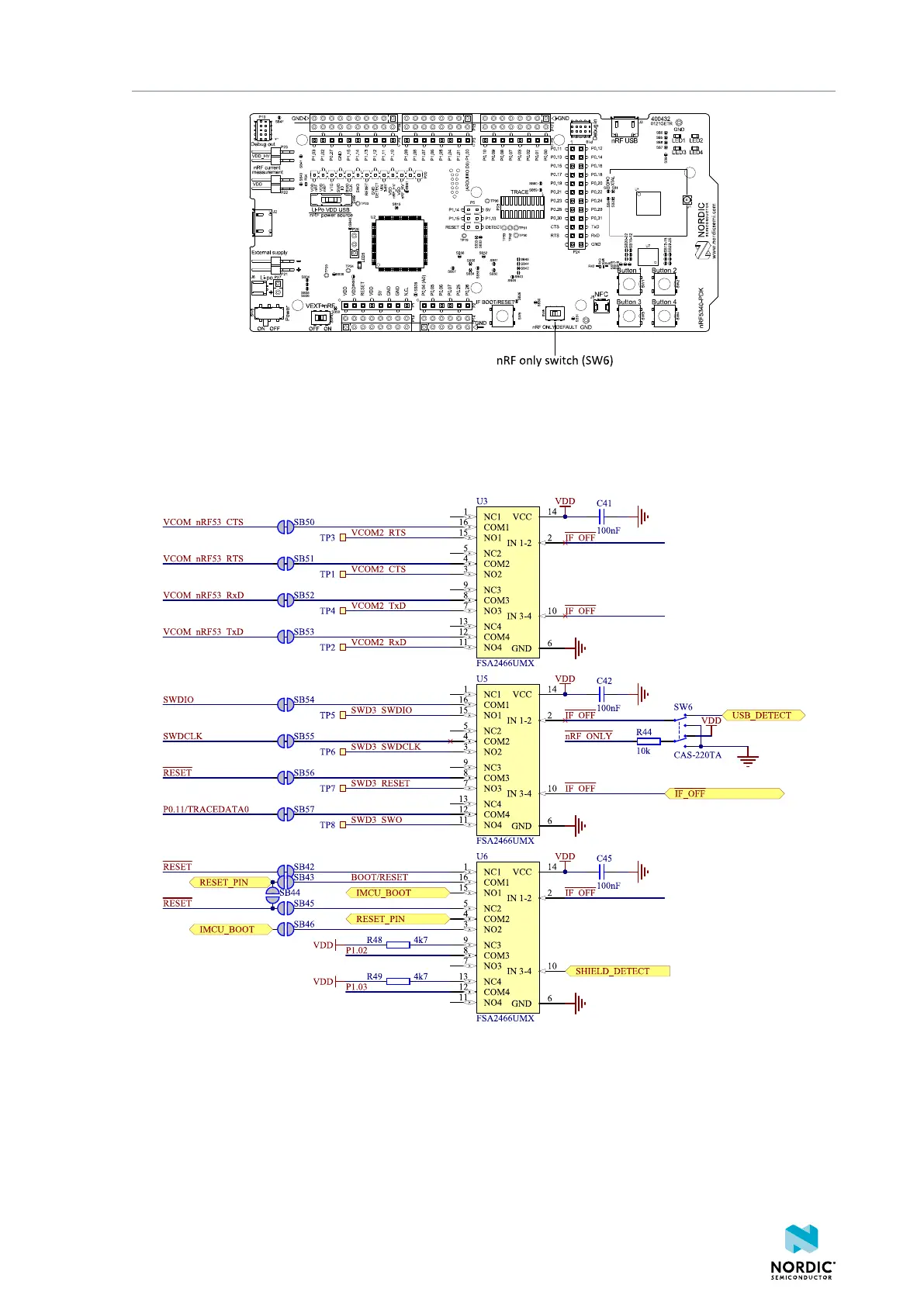
5.4.3 Signal switches
On the nRF5340 PDK board, there are multiple analog switches that are used to connect and disconnect
signals based on different scenarios.
Figure 17: Signal switches
The USB and SW6 control the signal switches by using USB_DETECT as an input to SW6. Therefore, the
interface MCU can be disconnected either by unplugging the USB cable in J2 or by toggling SW6.
The signal controls a set of switches (U3, U5, U6) that break the connection between the nRF5340 and the
interface MCU, and control the power for the interface MCU. For more information, see section Interface
MCU power on page 16.
4406_489 v1.0
20
 Loading...

