Hardware description
The nRF5340 SoC has a high voltage buck regulator that can support up to 5 V input. In the VDD position,
the SoC is powered either from the on-board buck regulator, coin cell battery, or external supply (P21).
In the Li-Po position, the high voltage regulator of the SoC is supplied directly from the Li-Po battery
connectors (J6 or P27). In the USB position, the USB high voltage regulator gets power from the nRF5340
USB connector (J3).
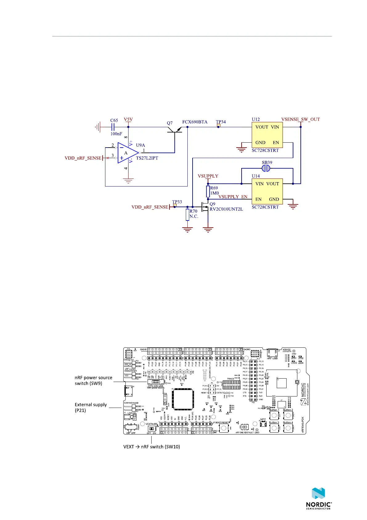
When the high voltage regulator is used, the VDD_nRF voltage can be set by the firmware of the SoC. To
make sure the rest of the board has the same voltage level, the VDD of the board is sourced by a regulator
following the VDD_nRF voltage when the high voltage regulator is used.
Figure 13: VDD_nRF voltage follower and switch
To make sure that the nRF5340 is not powered when the nRF power switch (SW8) is OFF, two load
switches are used, one for the high voltage regulator (U15) and one for the USB supply (U20). These
switches are controlled by VDD.
5.3.5 nRF5340 direct supply
It is possible to power the SoC directly from a source without powering the rest of the board from the
same source.
The external source can be connected to the external supply connector (P21) and the VEXT->nRF switch
(SW10) put in the ON position. The nRF power source switch (SW9) must be in the VDD position, and the
allowed voltage range is 1.7–3.6 V.
Figure 14: VEXT->nRF switch (SW10)
4406_489 v1.0
18

 Loading...
