Hardware description
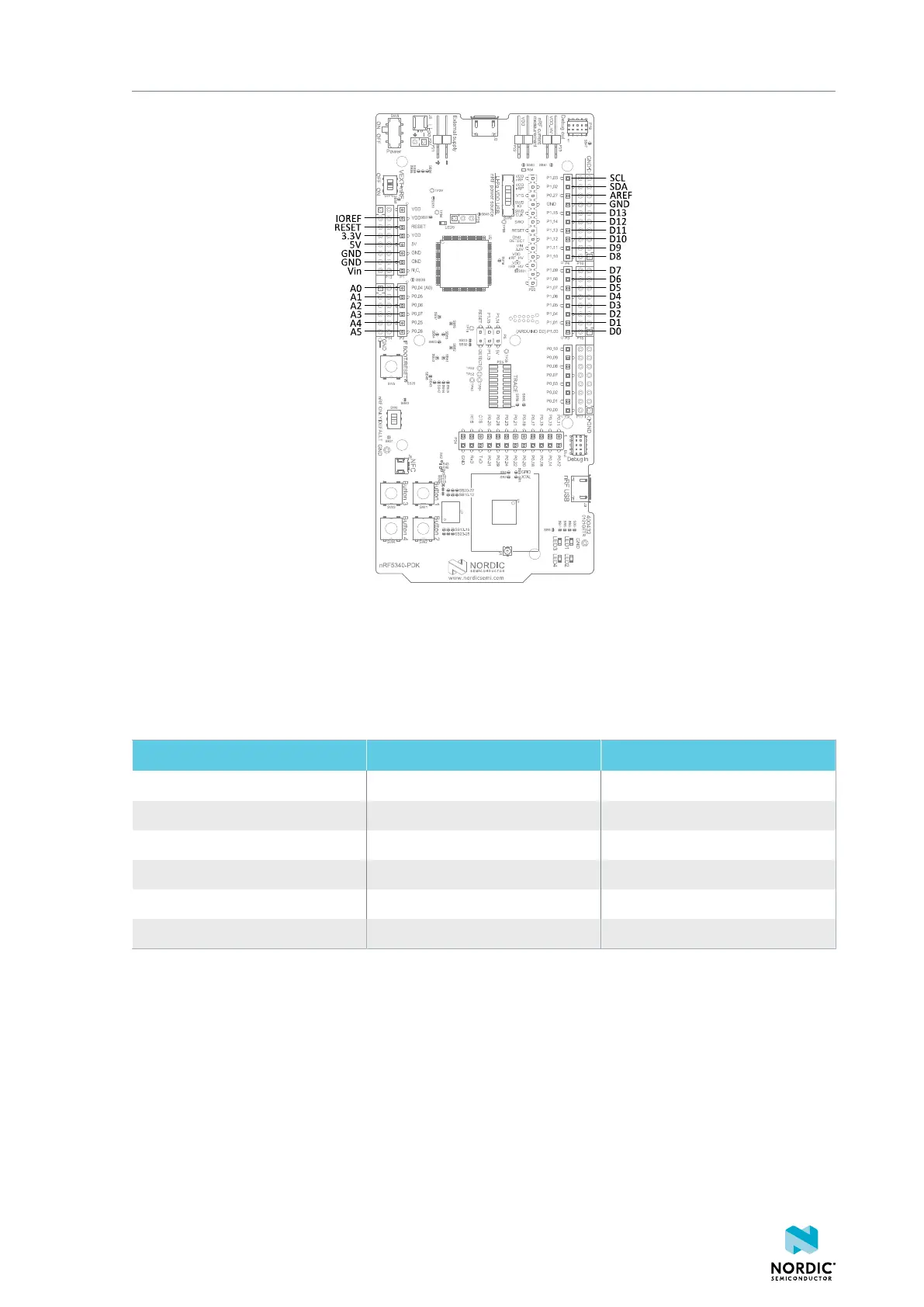
Figure 21: Arduino signals routing on the nRF5340 PDK board
5.6.1 Mapping of analog pins
The table shows the mapping between GPIO pins, analog inputs, and the corresponding Arduino analog
input naming.
GPIO Analog input Arduino naming
P0.04 AIN1 A0
P0.05 AIN2 A1
P0.06 AIN4 A2
P0.07 AIN5 A3
P0.25 AIN6 A4
P0.26 AIN7 A5
Table 5: Mapping of analog pins
5.7 Buttons and LEDs
The four buttons and four LEDs on the nRF5340 PDK board are connected to dedicated GPIOs on the
nRF5340 chip.
4406_489 v1.0
24

 Loading...
