Hardware description
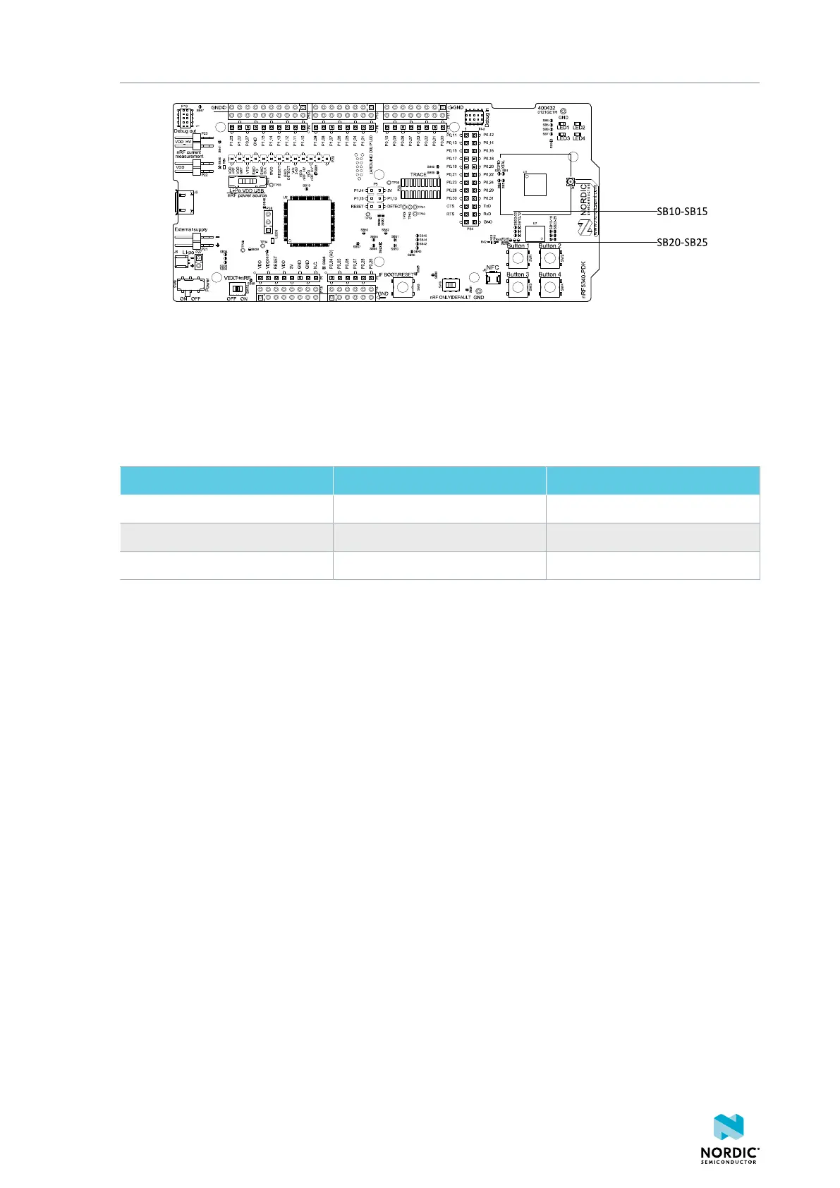
Figure 19: Configuring GPIOs for external memory
By default, the power supply of the external memory is coming from the VDD domain and it is controlled
by the nRF only switch (SW6). In the nRF only mode, there are two optional power sources for keeping
the external memory powered, VDD and VDD_nRF. If VDD_nRF is selected, the power consumption of the
external memory will be added to the nRF5340 current measured on P22 or P23. See the following table
for configuration:
Power source Solder bridge Default state
VDD_PER SB16 Shorted
VDD SB17 Open
VDD_nRF SB18 Open
Table 4: Flash memory power source configuration
5.6 Connector interface
Access to the nRF5340 GPIOs is available from connectors P2, P3, P4, P5, P6, and P24.
The P1 connector provides access to ground and power on the nRF5340 PDK board.
4406_489 v1.0
22

 Loading...
