Operating modes
3.2 Performance measurement mode
The performance measurement mode can be selected by moving the IFMCU DISCONN switch (SW1) to the
right position, which disconnects the interface MCU from the nRF9160 SiP using analog switches.
This is done to isolate the nRF9160 SiP as much as possible and can be of use when measuring currents on
low-power applications.
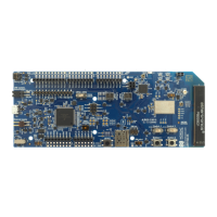
Figure 3: nRF9160 DK performance measurement mode
The development kit detects if there is a USB cable plugged in (see USB detect on page 11) and will
disconnect and power down the interface MCU when another supply than the USB is used. If the USB
connector is used for power supply only (USB battery back) you can also disable the interface MCU using
SW1.
USB detect and SW1 also control the routing of the RESET signal from the RESET button (SW2). Normally, it
is routed through the interface MCU, but if that is disabled, the reset button will be routed directly to the
nRF9160 SiP.
There are also a number of other reset routing options available through the use of solder bridges:
• When the interface MCU is disconnected, the RESET button is connected to pin 32 (nRESET) of the
nRF9160 SiP. The RESET button can be disconnected from the nRF9160 SiP by cutting SB25.
• When the interface MCU is disconnected, shorting SB29 will connect the RESET pin of the Arduino
interface to the reset pin of the nRF9160 SiP.
• When the interface MCU is connected, shorting SB30 will connect the RESET pin of the Arduino
interface to the BOOT input of the interface MCU.
• Shorting SB27 will connect the RESET pin of the Arduino interface to the RESET button.
• Shorting SB28 will connect the RESET pin of the Arduino interface to the nRESET pin of the nRF9160 SiP.
3.2.1 USB detect
To detect when the USB for the interface MCU is connected, there is a circuit sensing the VBUS of USB
connector J4.
When the USB cable is connected, the VDD is propagated to the USB_DETECT signal.
4418_1216 v0.9.1
11

 Loading...