EasyManuals Logo

Nordic nRF9160 DK User Manual

Nordic nRF9160 DK
44 pages
To Next Page IconTo Next Page
To Previous Page IconTo Previous Page
Page #13 background imageLoading...
Page #13 background image
4
Hardware description
The nRF9160 DK features an onboard programming and debugging solution.
4.1 Block diagram
The block diagram shows the main functionality of the nRF9160 DK.
nRF9160
GPS LNA/
BPF
Analog switch
Analog
switches
nRF52840
Analog
switches
Debug in
VDD IO switch Power switch
Power supply
circuitry
Interface MCU
IF MCU
Disconnect
switch
Debug out
Reset button
USB
connector
External
supply
LTE antenna
SIM
eSIM
(not mounted)
Prog. switch
Debug in
GPS antenna
2.4 GHz
antenna
LEDs
Buttons/
Switches
Connector
interface
U.FL
connector
Analog switch
Analog
switches
SWF
connector
SWF
connector
Antenna
select switch
SIM select
switch
Figure 5: nRF9160 DK block diagram
4.2 Hardware figures
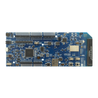
The nRF9160 DK hardware drawings show both sides of the PCA10090 board.
4418_1216 v0.9.1
13

Other manuals for Nordic nRF9160 DK

Questions and Answers:

Question and Answer IconNeed help?

Do you have a question about the Nordic nRF9160 DK and is the answer not in the manual?

Nordic nRF9160 DK Specifications

General IconGeneral
BrandNordic
ModelnRF9160 DK
CategoryMotherboard
LanguageEnglish