Hardware description
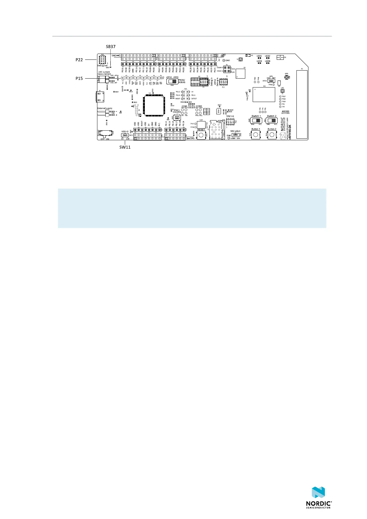
Figure 20: Debug output connector
When the external board is powered up, the interface MCU will detect the supply voltage of the board and
program/debug the target chip on the external board instead of the onboard nRF9160 and/or nRF52840.
Note: The voltage supported by external debugging/programming is the VDD voltage. This voltage
can be selected to 1.8 V or 3 V using slide switch SW11. For optimal performance of the nRF9160
radio, it is recommended that only 1.8 V is used. Make sure the voltage level of the external board
matches the VDD of the nRF9160 DK.
P15 can also be used as a debug out connector to program shield-mounted targets. For both P22 and P15,
the interface MCU will detect the supply voltage on the mounted shield and program/debug the target.
If the interface MCU detects target power on both P22 and P15, it will program/debug the target
connected to P22 by default.
If it is inconvenient to have a separate power supply on the external board, the nRF9160 DK can supply
power through the Debug out connector P22. To enable this, short solder bridge SB37.
4.10.1 Connectors for programming external boards
The voltage on the external board must match that of the DK.
4418_1216 v0.9.1
26
 Loading...