Hardware description
4.14 SiP enable
The SiP can be enabled or disabled by pulling pin 101 high and low.
By default, the enable signal is pulled high by resistor R3. To disable the SiP, connect to test point TP1 (on
the back of the board) and pull the pin low.
4.15 Solder bridge configuration
The nRF9160 DK has a range of solder bridges for enabling or disabling functionality on the board.
Changes to these are not needed for normal use of the development kit.
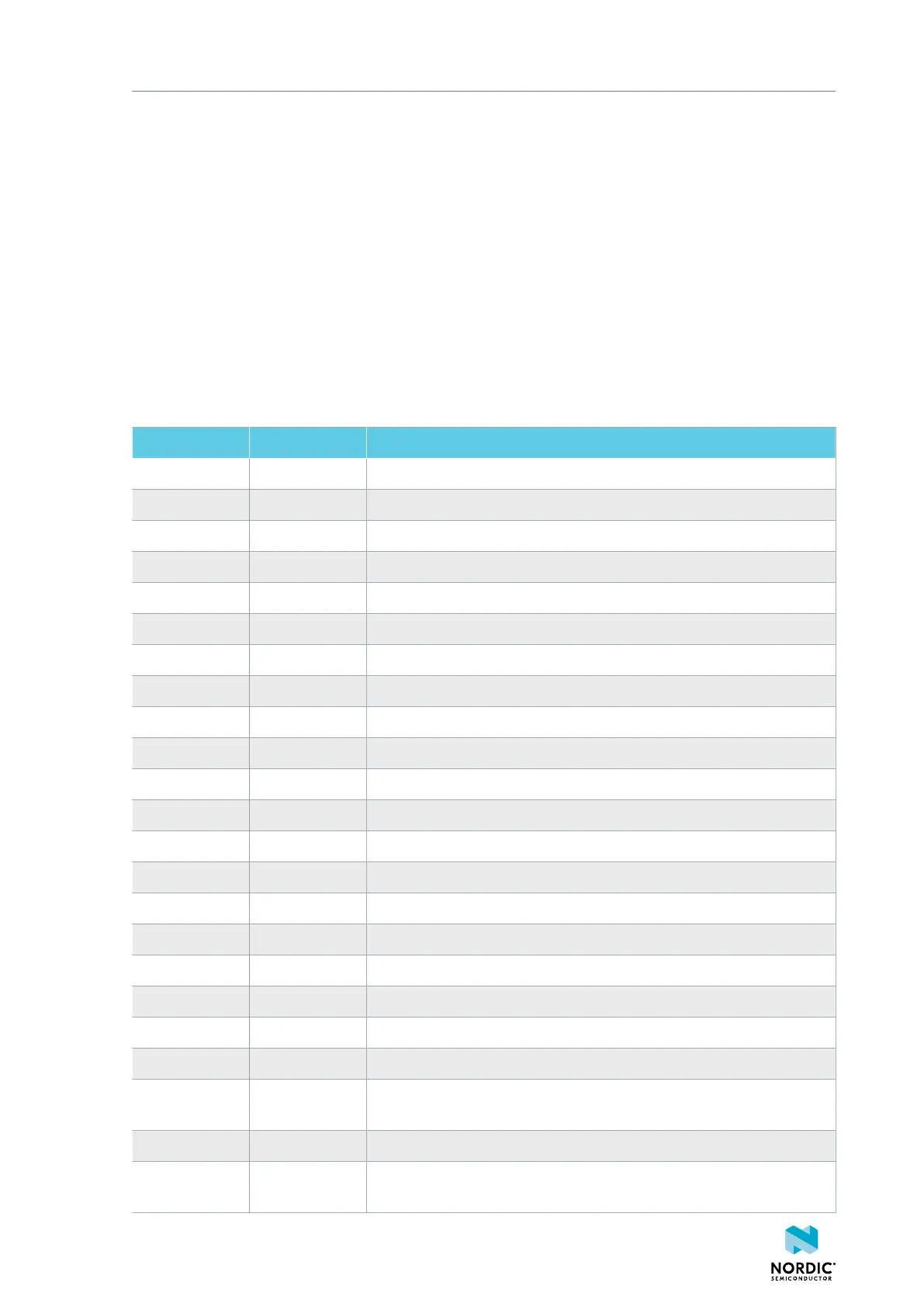
The following table is a complete overview of the solder bridges on the nRF9160 DK.
Solder bridge Default Function
SB2 Closed Cut to disconnect VDD_GPIO supply to the nRF9160 SiP
SB3 Open Short to bypass switch U26
SB4 Open Short to bypass the VIN3–5 V switch U31
SB5 Closed Cut to disconnect the RESET signal from the nRF52840 SoC
SB6 Closed Cut to disconnect RTS signal from the nRF52840 SoC
SB7 Closed Cut to disconnect CTS signal from the nRF52840 SoC
SB8 Closed Cut to disconnect RXD signal from the nRF52840 SoC
SB9 Closed Cut to disconnect TXD signal from the nRF52840 SoC
SB10 Closed Cut to disconnect SWDIO from the nRF52840 SoC
SB11 Closed Cut to disconnect SWDCLK from the nRF52840 SoC
SB12 Closed Cut to disconnect the 3.0 V USB supply from the interface MCU (U2)
SB13 Closed Cut to disconnect supply to LDO (U32)
SB14 Closed Cut to disconnect RTS from the nRF9160 SiP
SB15 Closed Cut to disconnect RTS from the nRF9160 SiP
SB16 Closed Cut to disconnect RXD from the nRF9160 SiP
SB17 Closed Cut to disconnect TXD from the nRF9160 SiP
SB21 Open Short to bypass the external supply switch U27
SB22 Closed Cut to disconnect supply from Arduino interface
SB23 Open Short to bypass Arduino 5 V reverse protection diode D3
SB24 Open Short to bypass the USB detect switch (Q3)
SB25 Closed Cut to disconnect the RESET button from the nRF9160 reset pin when
the interface MCU is disconnected
SB26 Closed Cut to disable the pull-up resistor of the RESET button (SW2)
SB27 Open Short to connect the RESET button to the RESET pin on the Arduino
interface
4418_1216 v0.9.1
34
 Loading...